
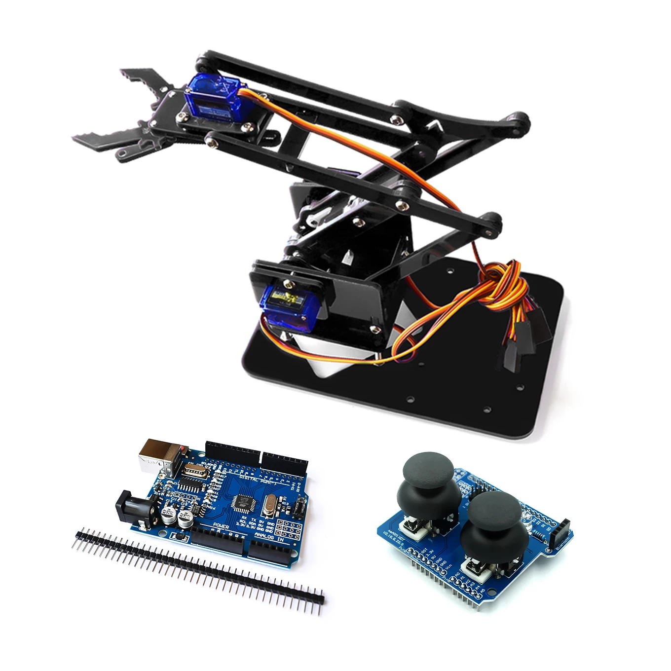
Joystick Robot Arm: 4-Axis Control with PCA9685
Control a joystick robot arm with a 4-axis joystick and a PCA9685 servo driver. The joystick gives three analog axes, X tilt, Y tilt, and Z twist, plus a momentary button on top, which the listing counts as the fourth axis. X maps to base rotation, Y maps to the shoulder, and Z twist maps to the elbow.
Quick facts
| Item | Value |
|---|---|
| Arm | 4-DOF acrylic arm kit with claw, 4 SG90 servos in the With SG90 option |
| Joystick | 4-axis potentiometer, 10 k, X Y tilt plus Z twist, top button; 3 analog outputs plus the button |
| Driver | PCA9685, 16 channels, I2C address 0x40 |
| Controller | Arduino Uno R3, 5 V logic |
| Joints | Base, shoulder, elbow, plus claw; 4 servos, no wrist joint |
| Servo supply | Separate 5 to 6 V, sized for stall current |
Joystick robot arm: what does each joystick axis control?
The joystick gives three analog signals, one per potentiometer, plus the top button. The X tilt controls the base rotation, so pushing the stick left and right spins the arm around its vertical axis. The Y tilt controls the shoulder, so pushing forward and back raises and lowers the upper arm. The Z twist controls the elbow, so twisting the stick bends the forearm. There is no fourth analog output on this joystick: the fourth axis in the product name is the momentary top button, and this arm kit has no wrist joint, so no wrist mapping exists. The button toggles the claw instead.
That mapping is a choice, not a law. If the twist feels wrong for the elbow, swap the elbow and shoulder assignments in the code. The mapping lives in three lines, one per joint, so changing it takes a minute. Keep the mapping you choose written on a card next to the joystick until it becomes habit.
The top button toggles the claw. Press once and the claw closes, press again and it opens. A toggle suits a claw, because holding a button down while the arm moves is awkward. The sketch debounces the button with a 200 ms debounce interval, so one press never registers as two.
How do you map a joystick reading to a servo angle?
Each joystick axis is a 10 k potentiometer, so the Uno analog pin reads 0 to 1023. Center is near 512. The sketch reads the pin, subtracts the center, and applies a dead zone of about 30 counts so a resting stick sends no motion. Outside the dead zone, the reading maps to a small angle step per loop, not to an absolute angle.
Relative control suits an arm. The stick sets the speed and direction of each joint, and the joint holds its position when the stick centers. Absolute control, where the stick position equals the joint angle, is simpler to code but twitchy in practice, because a small stick move swings the joint a long way.
Each joint has a safe angle range in the sketch. The base runs 0 to 180 degrees, the shoulder 30 to 150 degrees, and the elbow 30 to 150 degrees. The claw runs 20 to 160 degrees. Those limits keep the arm from driving its own joints into the table or past the servo end stops. Adjust them for your arm after the first test, and write the final numbers down.
How do you wire the joystick and the PCA9685?
The joystick has three analog outputs, one per potentiometer, plus a button output. The X and Y potentiometers end in solder tabs on the sides of the base, so solder wires to them and meter each wire before you connect it. The Z potentiometer comes prewired: red and white are the reference ends and black is the wiper. Wire each potentiometer as a voltage divider across the 5 V supply and read the wiper on an ADC pin: X wiper to A0, Y wiper to A1, and Z wiper (black wire) to A2. The top button has two blue wires: connect one to digital pin 2 and the other to ground, and use INPUT_PULLUP, so a press reads LOW.
The PCA9685 connects over I2C. Connect its VCC to the Uno 5 V pin, its GND to ground, its SDA to A4, and its SCL to A5. Connect the separate 5 to 6 V servo supply to the V+ screw terminal, and join the supply ground to the Uno ground. The servo plugs go on channels 0 to 3: base, shoulder, elbow, and claw.
Keep the joystick wires short and away from the servo power wires. Servo current spikes can couple into long analog wires and make the joints jitter. If a joint trembles with the stick centered, widen the dead zone from 30 to 50 counts before you change anything else.
How do you tune the arm so it moves smoothly?
Start with slow steps. The sketch moves each joint by at most 1 degree per 20 ms loop, which is about 50 degrees per second at full stick deflection. That is fast enough to feel responsive and slow enough to stay controllable. Raise the step to 2 degrees only after the arm tracks well at 1 degree.
Load changes everything. An empty claw moves freely, but a loaded claw sags the shoulder and elbow servos. Test with the load you plan to lift, not empty. If the shoulder sags under load, raise the servo supply from 5 V to 6 V, which adds torque, or reduce the load. Do not raise the supply above the servo 6 V rating for SG90 servos.
If the arm oscillates, the steps are too large or the dead zone is too small. Lower the step size first. If one joint alone oscillates, check its pulse calibration, because a pulse past the servo end stop makes the servo fight its own gears and buzz.
Wiring
Wire the build with the power off. Check every connection in the table before you connect any battery or USB cable.
| From | To | Notes |
|---|---|---|
| Joystick VCC | Uno 5 V | 10 k potentiometers, 5 V logic |
| Joystick GND | Uno GND | Common ground |
| Joystick X wiper | Uno A0 | Base rotation, analog 0 to 1023; solder tabs on the base, meter before soldering |
| Joystick Y wiper | Uno A1 | Shoulder, analog 0 to 1023; solder tabs on the base, meter before soldering |
| Joystick Z wiper, black wire | Uno A2 | Elbow, analog 0 to 1023; red and white are the reference ends |
| Joystick top button, blue wires | Uno digital pin 2 and GND | Claw toggle; INPUT_PULLUP, press reads LOW |
| PCA9685 VCC | Uno 5 V | Logic only, a few milliamps |
| PCA9685 GND | Uno GND and servo supply negative | Common ground for all three |
| PCA9685 SDA | Uno A4 | I2C data |
| PCA9685 SCL | Uno A5 | I2C clock |
| PCA9685 V+ screw terminal | Separate 5 to 6 V supply positive | Servo power only; size for stall current |
| PCA9685 channel 0 | Base servo | Signal, V+, GND |
| PCA9685 channel 1 | Shoulder servo | Signal, V+, GND |
| PCA9685 channel 2 | Elbow servo | Signal, V+, GND |
| PCA9685 channel 3 | Claw servo | Signal, V+, GND; toggled by the top button |
Power budget
The logic side draws only a few milliamps from the Uno 5 V pin: the joystick potentiometers and the PCA9685 chip. The servo side draws whatever the servos demand. Four micro servos moving together draw on the order of 1 A under light load, and far more when they start or stall together.
Use a separate 5 to 6 V supply rated at 3 A or more for the V+ terminal. Never power the servos from the Uno 5 V pin. The Uno regulator supplies about 500 mA from USB, and a single stalled micro servo can exceed that. The board will reset and the arm will drop. No authoritative TowerPro datasheet publishes an SG90 stall current, so do not size the supply from a single stall number: the 3 A rating above is a planning rating with headroom, and meter your own servos if you need an exact figure.
Add a 470 to 1000 microfarad capacitor across V+ and ground at the terminal. The servos draw sharp spikes when they start moving, and the capacitor absorbs them. Without it, the rail sags and every joint jitters at once.
Build steps
- Assemble the 4-DOF acrylic arm kit with the claw. Fit the 4 SG90 servos and confirm each joint moves freely by hand before you power anything. Buy the With SG90 option: the Arm Only option ships as acrylic parts and screws with no servos.
- Mount the PCA9685 near the arm base. Connect the four servos to channels 0 to 3 in base, shoulder, elbow, and claw order.
- Wire the joystick to the Uno analog pins and the button to digital pin 2 from the wiring table.
- Wire the PCA9685 I2C pins and the separate servo supply. Join the supply ground to the Uno ground. Leave the servo supply off for now.
- Install the Adafruit PWM Servo Driver library. Upload the sketch below with the servo supply still off.
- Switch the servo supply on. The arm should park at its home position: base 90, shoulder 90, elbow 90, claw open.
- Push the stick in each direction and confirm the right joint moves. Press the top button and confirm the claw toggles. Calibrate the pulse limits per joint until no servo buzzes at its ends.
Code
Library: Adafruit PWM Servo Driver library. Board: Arduino Uno R3. Each joystick axis drives one joint in relative steps, and the top button toggles the claw. The joystick has three analog axes, so the claw is the only joint on the button; the kit has no wrist joint.
// Joystick robot arm: 4-axis joystick + PCA9685, 4 servos
// Board: Arduino Uno R3. Library: Adafruit PWM Servo Driver.
#include
#include

Adafruit_PWMServoDriver pwm = Adafruit_PWMServoDriver(0x40);

#define SERVOMIN 150   // About 730 microseconds at 50 Hz; calibrate per servo
#define SERVOMAX 600   // About 2930 microseconds at 50 Hz; calibrate per servo
#define SERVO_FREQ 50

const int JOY_X = A0;  // Base
const int JOY_Y = A1;  // Shoulder
const int JOY_Z = A2;  // Elbow
const int BTN_PIN = 2; // Claw toggle, INPUT_PULLUP

const uint8_t CH_BASE = 0, CH_SHOULDER = 1, CH_ELBOW = 2;
const uint8_t CH_CLAW = 3;

// Safe joint ranges in degrees. Adjust for your arm after testing.
const int LIM[4][2] = {{0, 180}, {30, 150}, {30, 150}, {20, 160}};
int angle[4] = {90, 90, 90, 20};  // Start parked, claw open
bool clawClosed = false;
unsigned long lastBtnMs = 0;

uint16_t angleToPulse(int a) {
  return map(constrain(a, 0, 180), 0, 180, SERVOMIN, SERVOMAX);
}

void setServo(uint8_t ch, int a) {
  pwm.setPWM(ch, 0, angleToPulse(a));
}

// Read one joystick axis and return a step of -1, 0, or +1.
int readStep(int pin) {
  int v = analogRead(pin) - 512;  // Center is near 512
  if (v > 30) return 1;           // Dead zone of 30 counts
  if (v < -30) return -1;
  return 0;
}

void moveJoint(uint8_t ch, int step) {
  if (step == 0) return;
  angle[ch] = constrain(angle[ch] + step, LIM[ch][0], LIM[ch][1]);
  setServo(ch, angle[ch]);
}

void setup() {
  Serial.begin(115200);
  pinMode(BTN_PIN, INPUT_PULLUP);
  pwm.begin();
  pwm.setOscillatorFrequency(27000000);
  pwm.setPWMFreq(SERVO_FREQ);
  delay(10);
  for (uint8_t ch = 0; ch < 4; ch++) setServo(ch, angle[ch]);
}

void loop() {
  moveJoint(CH_BASE, readStep(JOY_X));
  moveJoint(CH_SHOULDER, readStep(JOY_Y));
  moveJoint(CH_ELBOW, readStep(JOY_Z));

  // Top button toggles the claw, debounced by 200 ms.
  if (digitalRead(BTN_PIN) == LOW && millis() - lastBtnMs > 200) {
    lastBtnMs = millis();
    clawClosed = !clawClosed;
    angle[CH_CLAW] = clawClosed ? LIM[CH_CLAW][1] : LIM[CH_CLAW][0];
    setServo(CH_CLAW, angle[CH_CLAW]);
  }
  delay(20);  // About 1 degree per 20 ms at full deflection
}
Test and tune it
Center the stick and confirm all joints hold still. A joint that creeps with a centered stick has a joystick reading outside the dead zone. Widen the dead zone from 30 to 50 counts.
Move each joint to both ends of its range. A servo that buzzes at an end is past its mechanical limit. Lower the limit in the LIM table for that joint until the buzz stops.
Pick up a light object with the claw and hold it for 30 seconds. If the shoulder sags, raise the servo supply from 5 V to 6 V or reduce the load. Do not exceed the SG90 6 V rating.
FAQ
Which joystick axis controls which joint?
X controls the base, Y controls the shoulder, and Z twist controls the elbow. The top button toggles the claw. There is no fourth analog axis and no wrist joint on this kit: the fourth axis in the product name is the top button. Swap the assignments in the code if another mapping feels better.
Why does the arm jitter when the stick is centered?
The joystick reading sits outside the dead zone, or servo current spikes are coupling into the analog wires. Widen the dead zone to 50 counts and keep the joystick wires away from the servo power wires.
Why does the arm drop when I power it on?
The servos have no holding torque until the sketch parks them, and the Uno 5 V pin cannot hold them under load. Power the servos from the separate V+ supply and let the sketch park the arm at startup.
Can I use MG996R servos on this arm?
Only if the arm frame and the supply suit them. An MG996R draws up to 2.5 A at stall on 6 V, so four of them need a far larger supply than four SG90 servos. Check the arm kit servo mounts first.
How do I stop a joint from hitting the table?
Set its safe range in the LIM table in the sketch. The shoulder and elbow limits of 30 to 150 degrees keep the arm from driving its joints into the table or past the servo end stops.
Parts used
Build it with the 4-Axis Joystick Potentiometer with Momentary Top Button, 10K, X Y Tilt plus Z Twist, for Arduino, ESP32, and Robot Projects, the PCA9685 16-Channel PWM Servo Driver Board, 12-Bit IIC Interface, Arduino + Raspberry Pi, 2-Pack, and the 4-DOF Acrylic Robot Arm Kit with Claw for Arduino, Unassembled, SG90 / UNO / Rocker Options. For a servo arm build without the driver board, see How to Build a Robot Arm with ESP32 and Servo Motors, and the servo signal behind the positions is Digital vs Analog Servo Guide: Which Servo Holds Center.
Sources
Last updated: 2026-11-21. Search volume: not verified. Product links use the store short link form with the product ID; confirm the product slug at publish time.