A4988 vs DRV8825 vs TMC2209: Which Stepper Driver Wins

Buy the TMC2209 for any new 3D printer or CNC build that runs in a room with people in it. Buy the DRV8825 when the axis needs more than 29 V and noise does not matter. Buy the A4988 only when the budget is the whole decision, or when you are replacing a dead A4988 in a machine that already works. All three are bipolar stepper chopper drivers on the StepStick footprint. Source: QRC posts 16272 and 23584.

A4988 vs DRV8825 vs TMC2209 at a glance

Feature A4988 (Allegro) DRV8825 (TI) TMC2209 (Trinamic/ADI)
Max continuous current 1.0 A/phase (2.0 A max, cooled) 1.5 A/coil (2.5 A chip max, heatsinked) 2.0 A RMS, 2.8 A peak/coil
Max microstepping 1/16 1/32 1/256 interpolated
Noise Loud PWM whine Very loud harsh chopping Silent StealthChop2
Configuration Jumpers, VREF pot Jumpers, VREF pot UART or jumpers
Sensorless stall detection No No Yes, StallGuard4 via UART
Voltage range 8 to 35 V 8.2 to 45 V 4.75 to 29 V chip, 4.75 to 28 V listing
Best use Basic prototyping, low-cost plotters Standard 3D printers, light CNC, high voltage axes Silent operation, sensorless homing

Sources: QRC post 16272; Allegro A4988, TI DRV8825, and Trinamic TMC2209 datasheets; QRC listings 17896, 23573, and 19618.

When does the A4988 win?

The A4988 wins on price and on nothing else. It is the cheapest way into stepper control and the workhorse of a decade of RepRap printers. The QRC single module costs $6.99 and includes a heatsink. Its limits are real: 1 A per phase without a heatsink, 2 A max with cooling, per the Allegro datasheet, and the QRC listing states up to 1.2 A continuous per phase. It thermally throttles at roughly 1.2 A without a heatsink, it stops at 1/16 microstepping, its fixed-decay chopping buzzes at low speed, and it runs on 5 V logic, with 3.3 V unreliable, so an ESP32 build needs level shifting. Source: QRC post 16272; QRC listing 17896; ElectricalFlux ESP32 guide. Buy it when the motor is small, the budget is tight, and the noise does not matter. Do not buy it for a printer on a desk or any motor above 1.2 A per phase.

When does the DRV8825 win?

The DRV8825 wins when the axis needs voltage or current the A4988 cannot give, and the TMC2209 ceiling is in the way. Its motor supply runs 8.2 V to 45 V, the widest range of the three, so it is the only one that handles a 36 V axis or a high-speed CNC axis. It is rated 1.5 A per coil, with a chip maximum of 2.5 A per coil with proper heatsinking at 24 V and 25 C, per the TI datasheet. The QRC listing adds one more chip figure: 1.75 A RMS per coil with proper heatsinking. Source: QRC post 16272; TI DRV8825 datasheet SLVSA73F; QRC listing 23573. Its microstepping runs full step to 1/32 step, set with the M0, M1, and M2 pins. One mapping difference matters when swapping from an A4988: the setting that gives 1/16 step on the A4988 gives 1/32 step on the DRV8825. Buy it for a standard 3D printer axis, a light CNC axis, or any axis above 29 V. Do not buy it for a silent build: it is the loudest of the three.

When does the TMC2209 win?

The TMC2209 wins for any new build in 2026 where the machine runs near people. StealthChop2 removes the high-pitch whine of the older drivers, StallGuard4 lets the axis home with no endstop switch, and CoolStep cuts the current automatically when the load is light. Its current rating is 2 A RMS and 2.8 A peak per coil, per the Trinamic TMC2209 datasheet Rev 1.05, and the QRC 5-pack listing states the same figures. That is the highest continuous current of the three, and it is an RMS figure, not a peak figure. Source: QRC post 16272; Trinamic datasheet Rev 1.05; QRC listing 19618. Its limits are the voltage ceiling and the setup effort: the chip tops out at 29 V, and the store listing states 4.75 to 28 V, so a 36 V axis belongs on the DRV8825, and UART needs a wire and a firmware change. Once configured, current, microstepping, and mode change in firmware. Source: QRC post 16272; Sounds Electric TMC2209 guide. Buy it for a 3D printer, a CNC machine in a shared room, or any build that needs sensorless homing. Do not buy it for an axis above 28 V, or for a NEMA 23 motor over 2 A RMS per coil: that job belongs to a larger external driver such as the DM542 in post 16272.

Current compared: the RMS versus peak trap

The three current ratings look comparable in a table. They are not, because they are measured differently. The A4988 and DRV8825 formulas set a peak current: the top of the sine wave each coil sees during microstepping. The TMC2209 formula sets an RMS current: the heating value of that sine wave, about 70.7 percent of the peak. So 1 A on a TMC2209 is not the same setting as 1 A on an A4988: the TMC2209 at 1 A RMS pushes each coil to a 1.41 A peak. Source: The Science 360 VREF guide; Trinamic datasheet Rev 1.05 via BIGTREETECH. Size the driver from the motor rated phase current with headroom, not from the headline number. The rule from QRC post 16272 is: driver continuous current must be at least 1.5 times the motor continuous running current, and peak current must cover the stall current. A 1.5 A NEMA 17 needs a driver that holds 1.5 A continuously: the A4988 at 1 A cannot do it, the DRV8825 at 1.5 A is borderline and runs hot without a fan, and the TMC2209 at 2 A RMS handles it with margin.

Microstepping compared: resolution is not accuracy

Microstepping splits each full step into smaller steps, which makes motion smoother and quieter. It does not add holding torque, and it does not add positioning accuracy in the way the numbers suggest. A 1.8 degree stepper is accurate to about plus or minus 5 percent of a full step no matter how finely you slice it. The A4988 runs full step to 1/16 step (200 to 3,200 steps per rev on a 1.8 degree motor), the DRV8825 runs full step to 1/32 step (200 to 6,400), and the TMC2209 runs to 1/256 interpolated steps (up to 51,200) through MicroPlyer interpolation, which smooths incoming step signals up to 256 subdivisions. Full-step mode gives the most torque per step on every driver, so if an axis loses steps at high microstepping, dropping back to a coarser step setting is a legitimate fix. Source: QRC post 16272; Sounds Electric TMC2209 guide. Do not pick a driver for its microstepping number alone: a 1/256 driver on a machine with a loose belt and a wobbling frame still prints wobble.

Noise compared: why the old drivers whine

The A4988 and the DRV8825 chop the motor current with a fixed-decay chopper whose switching frequency falls in the human hearing range, typically 2 kHz to 20 kHz. The motor turns that switching into a constant whine during every move, with the pitch shifting with speed. Higher VREF settings and low microstepping make it worse. Source: ElectricalFlux stepper driver module guide; Sounds Electric TMC2209 guide. The TMC2209 fixes this two ways. StealthChop2 is a voltage-mode PWM chopper that keeps the motor near silent at low and medium speeds. SpreadCycle is a current-mode chopper that gives higher torque for rapid moves, at the cost of more noise. The driver switches between them, so print moves stay quiet and travel moves keep their torque. The A4988 and DRV8825 have no equivalent: their only noise fix is more microstepping, which helps a little and never reaches silence. Source: Sounds Electric guide; QRC post 16272.

Heat compared: where the current goes

Every amp a chopper driver regulates turns partly into heat in the chip. The A4988 thermally throttles at roughly 1.2 A without a heatsink. The DRV8825 needs a heatsink plus airflow above about 1.5 A per coil, or the chip throttles on temperature. The TMC2209 runs cooler at the same load because CoolStep cuts the current when the load is light. Source: ElectricalFlux stepper driver module guide; QRC listings 17896 and 23573; Sounds Electric TMC2209 guide. For all three: fit the heatsink, keep air moving across the driver bank, and never treat the headline current as a continuous rating. A driver that stops after three minutes, then works again after cooling, has hit thermal shutdown. Source: ElectricalFlux module guide.

How to set the current limit: VREF, worked examples

Set the current limit before connecting the motor. The A4988 and the DRV8825 set it with a trim potentiometer: measure VREF between the VREF pin and ground while turning the pot. The TMC2209 sets it in software over UART. Source: QRC post 16272; The Science 360 VREF guide.

Read the sense resistor first. The formula depends on the sense resistor printed on your board, not just on the chip. The sense resistors are two small black parts near the chip, printed with a code such as R068, R100, or R110: R068 is 0.068 ohm, R100 is 0.100 ohm, R110 is 0.110 ohm. Read your own resistors before copying a number from any guide. Source: The Science 360 VREF guide; Pololu carrier pages.

Driver Formula Worked example
A4988 VREF = 8 x Rs x I 1 A limit: 0.544 V on R068, 0.400 V on R050, 0.8 V on R100. Start at about 70 percent of the motor rated current
DRV8825 VREF = 5 x Rs x I; on a Pololu carrier with R100 resistors, current limit = VREF x 2 1.5 A NEMA 17: VREF = 0.75 V on a Pololu carrier. The x2 shortcut is Pololu-carrier specific
TMC2209 Over UART: set in software with the irun register. Standalone: VREF is about 1.41 x the RMS current on R110 boards 0.8 A RMS: VREF = 1.131 V; pot tops out near 1.77 A RMS

Sources: Allegro and TI datasheets via The Science 360 VREF guide; Pololu carrier pages; BIGTREETECH wiki; QRC post 16272.

How to wire all three

All three share the StepStick footprint. The full A4988 wiring table lives in QRC post 16272. The DRV8825 drops into the same socket, with the same STEP, DIR, VMOT, VDD, and coil pins, and these differences: M0, M1, and M2 instead of MS1, MS2, and MS3, an nFAULT pin, a DECAY pin, and SLEEP and RESET pins in place of SLP and RST. The TMC2209 drops into the same socket too: PDN_UART carries the single-wire UART link, and DIAG signals a stall for sensorless homing. In standalone mode, MS1 and MS2 set the microstepping and the pot sets the current. With UART, firmware sets the current, microstepping, chopper mode, and StallGuard4 threshold. Source: QRC listings 23573 and 19618; QRC post 16272.

DRV8825 microstepping table

M0 M1 M2 Resolution
LOW LOW LOW Full step
HIGH LOW LOW Half step
LOW HIGH LOW 1/4 step
HIGH HIGH LOW 1/8 step
LOW LOW HIGH 1/16 step
HIGH LOW HIGH 1/32 step
LOW HIGH HIGH 1/32 step
HIGH HIGH HIGH 1/32 step

Source: QRC product listing 23573. Note the trap: the M0-M2 setting that gives 1/16 step on the A4988 gives 1/32 step on the DRV8825.

Coil pairing and the bulk capacitor

Find the coil pairs with a multimeter: two wires that show a low resistance between them, typically 1 to 5 ohms, are one coil. Connect coil 1 to 1A and 1B, and coil 2 to 2A and 2B. Fit a bulk capacitor across the motor supply near the driver when the supply leads are long: for A4988 boards, fit at least a 47 uF electrolytic capacitor across VMOT and GND, close to the driver. Without it, voltage spikes can exceed 35 V at VMOT even from a 12 V supply and destroy the driver on power-up. Join the grounds, never unplug a motor cable while powered, and do not leave STEP or DIR floating. Source: QRC post 16272.

Which driver should I buy? The decision table

Your build Pick Why
New 3D printer, desk or bedroom TMC2209 Silent, sensorless homing
3D printer axis above 28 V DRV8825 45 V ceiling
Light CNC axis, 12 to 24 V DRV8825 1.5 A per coil, widest range
Classroom set of 10 drivers A4988 Cheapest per driver
ESP32 build at 3.3 V logic TMC2209 3.3 to 5 V native
NEMA 23 motor over 2 A per coil None of the three Step up to a DM542

What are the common mistakes?

  • Setting VREF from a guide without reading the sense resistor. A 0.544 V setting for a 1 A limit is correct only on a Pololu-style A4988 carrier with 0.068 ohm resistors. Read the R-code first.
  • Using the DRV8825 x2 shortcut on the wrong board. Current limit = VREF x 2 holds only on a Pololu carrier with 0.100 ohm resistors.
  • Comparing a TMC2209 RMS current with an A4988 peak current. 1 A RMS on a TMC2209 pushes each coil to a 1.41 A peak.
  • Swapping an A4988 for a DRV8825 without re-checking the microstep table. The setting that gives 1/16 step on the A4988 gives 1/32 step on the DRV8825.
  • Running an A4988 at the motor full rated current with no heatsink or airflow. It thermally throttles near 1.2 A without a heatsink.

How do I fix a stepper driver problem?

The motor hums and vibrates but does not spin. The coil pairs are mismatched, or VREF is too low. Rewire the coil pairs with a multimeter, then raise VREF in 0.1 V steps.

The driver is too hot to touch, or the motor stops after a few minutes and works again after cooling. The driver hit thermal shutdown. Lower VREF, fit the heatsink, and put a fan across the driver bank. Source: ElectricalFlux module guide.

The motor stalls or skips steps mid-move. The ramp is too aggressive, or the axis hit mid-band resonance at about 2 to 4 revolutions per second. Slow the ramp, change microstepping, or switch to a TMC2209.

The motor moves half as far per step as expected after a driver swap. You swapped an A4988 for a DRV8825 without changing the mode pins. Check the DRV8825 microstepping table above.

Parts used in this guide

Prices and stock were verified live on qualityrcparts.com on 2026-11-21. All three items are in stock and purchasable.

Shipped fast and securely from our secure facility in Queensbury, NY. QRC ships within the USA only.

Related guides

FAQ

Which stepper driver is best for a 3D printer, A4988, DRV8825, or TMC2209? The TMC2209: near silent with StealthChop2, 2 A RMS per coil, and StallGuard4 sensorless homing. The DRV8825 is the pick only above 28 V. Source: QRC post 16272.

Can I replace an A4988 with a TMC2209? Yes, all three share the StepStick footprint. Re-check the microstepping pins and the current setting: TMC2209 figures are RMS, A4988 figures are peak.

What VREF should I set on an A4988? VREF = 8 x Rs x I. On a Pololu carrier with 0.068 ohm resistors, 0.544 V gives a 1 A limit; on a 0.100 ohm board, 0.8 V gives 1 A.

What VREF should I set on a DRV8825? On a Pololu carrier with 0.100 ohm resistors, current limit = VREF x 2, so a 1.5 A NEMA 17 needs 0.75 V. That shortcut is Pololu-carrier specific.

Does the TMC2209 need VREF? Not over UART: the current is set in software with the irun register. In standalone mode, on 0.110 ohm boards, VREF is about 1.41 times the RMS current you want.

Why does my stepper motor lose steps? The load torque passed what the motor can deliver at that speed, the ramp is too fast, or the axis hit mid-band resonance at about 2 to 4 revolutions per second. Slow the ramp, change microstepping, or switch to a TMC2209.

Sources

Last updated: 2026-11-21

Types of Motor Drivers: H-Bridge, Stepper, and BLDC

The type of motor driver you need is decided by the motor, not by the microcontroller: a brushed DC motor needs an H-bridge, a stepper motor needs a chopper driver, a brushless motor needs a three-phase ESC, and a hobby servo needs no driver board at all. Pick the type first, then pick the chip.

What is a motor driver?

A motor driver is the circuit between a low-power control signal and a motor that needs real power. An Arduino pin can supply only about 20 to 40 mA, while even a small TT gear motor draws 150 to 250 mA running and close to 1 A stalled. Connect a motor straight to a pin and the pin burns out. A motor driver keeps the high motor current off the board. Source: QRC post 16272.

Every driver type does the same three jobs in a different way: it switches power to the motor windings, controls speed or position, and protects the board and the motor from spikes. The differences come from what the motor needs switched: a brushed DC motor needs its two wires flipped in polarity, a stepper motor needs its two coils energized in sequence with the current capped, and a brushless motor needs three phases energized in a rotating sequence timed to the rotor. Those three switching jobs are three different driver types, and they are not interchangeable.

What are the types of motor drivers?

Six types cover nearly every Arduino and hobby build.

Driver type Motor it runs Control signal Best for
Brushed DC H-bridge Brushed DC motor PWM plus direction pins Robot wheels, gear motors, winches, pumps
Stepper chopper Bipolar stepper motor STEP and DIR pulses 3D printers, CNC axes, camera sliders
BLDC driver / ESC Brushless DC motor PWM, PPM, or DShot throttle Drones, RC cars, fans, gimbals
Servo control Hobby RC servo Position PWM signal Robot arms, steering, control surfaces
Single-direction switch Any one-way DC load One logic pin Fans, one-way pumps, solenoids
Smart driver DC, stepper, or BLDC SPI, I2C, UART, or STEP/DIR Builds that need stall detection or telemetry

Sources: Number Analytics, ElecBlog, ThinkRobotics, Schneider Electric.

How does a brushed DC H-bridge driver work?

A brushed DC motor spins when voltage is applied across its two wires and reverses when the polarity flips. An H-bridge is four switches in the shape of the letter H, with the motor as the crossbar: one diagonal pair drives current one way, the other pair the other way. Source: ThinkRobotics motor driver basics; ElecBlog motor driver selection guide.

Two switch technologies do this job. Bipolar H-bridges, such as the L298N, use bipolar transistors: the ST L298 datasheet DS0218 Rev 5 lists a total saturation drop of 1.8 V to 3.2 V at 1 A, so on a 7.4 V battery the motor sees about 4.2 V to 5.6 V. MOSFET H-bridges, such as the TB6612FNG and DRV8833, use MOSFETs: the Toshiba TB6612FNG datasheet lists about 0.5 ohm total on-resistance, so at 1 A it drops about 0.5 V, and the TI DRV8833 datasheet SLVSAR1E Rev E lists about 0.36 ohm, so at 1 A it drops about 0.36 V. A MOSFET driver delivers nearly the full battery voltage to the motor. Source: QRC post 23379; ST L298, Toshiba TB6612FNG, and TI DRV8833 datasheets.

Never turn on both switches on the same side at once: that shorts the supply to ground, a fault called shoot-through, and it destroys the switches. An H-bridge also decides how the motor stops: shorting the terminals brakes the motor fast, and letting them float lets it coast. Source: ElecBlog motor driver selection guide; TrueGeometry motor driver circuits guide; QRC post 16272.

How does a stepper chopper driver work?

A stepper motor moves in fixed angles as its coils are energized in sequence. A stepper driver takes two signals, STEP and DIR, and handles the coil sequencing itself. Source: ElecBlog motor driver selection guide; QRC post 16272.

What makes a stepper driver a different TYPE is current chopping. A stepper coil is a low-resistance winding that would draw far more current than it is rated for at the supply voltage. The driver measures the coil current and switches off the instant it reaches the rated limit, then switches back on, thousands of times per second. That holds the coil at its rated current while the supply runs much higher than the motor rated voltage, so a low-voltage NEMA 17 runs safely from 12 V or 24 V. A DC H-bridge has no current limit, so the supply voltage must stay near the motor rating. Source: QRC post 16272; ElecBlog motor driver selection guide.

Microstepping. A chopper driver can split each full step into smaller steps. The A4988 runs full step to 1/16 step, the DRV8825 runs full step to 1/32 step, and the TMC2209 runs to 1/256 interpolated steps. Microstepping makes motion smoother and quieter, but it does not add holding torque. The A4988 listing states up to 1.2 A continuous per phase, and the DRV8825 listing states 1.5 A per coil, with the chip maximum at 2.5 A per coil with heatsinking at 24 V and 25 C. Set the current limit with the onboard trim potentiometer before connecting the motor. Source: QRC product listings 17896 and 23573; QRC post 16272.

How does a BLDC driver work?

A brushless DC motor has no brushes and no mechanical commutator. The magnets sit on the rotor and the windings sit on the stator, so the driver must commutate electronically, switching current between the three phases in a rotating sequence timed to the rotor position. The power stage is a three-phase inverter: three half-bridges, six switches in total. No H-bridge board in this guide can run a brushless motor: if your motor has three wires and no brushes, shop for an ESC, not a driver module. Source: ElecBlog motor driver selection guide; MIKROE motor control basics guide; QRC post 16272.

Six-step vs field-oriented control. The basic method is six-step, also called trapezoidal drive: two phases conduct at a time and the third floats, which works but produces torque ripple. The advanced method is field-oriented control (FOC), which controls torque and flux separately for smooth torque, high efficiency, and full torque at zero speed. FOC needs position feedback and clean phase-current sensing. For a hobby drone or RC car, six-step is the normal choice; for a gimbal, FOC is worth it. Source: MIKROE motor control basics guide; Wevolver motor controller guide.

Sensored vs sensorless. The driver must know where the rotor is to time the phase switching. Sensored drivers read Hall-effect sensors and start reliably at low speed. Sensorless drivers read back-EMF from the unpowered phase, which works once the motor is spinning but is unreliable at a standstill, so a sensorless ESC that stutters on startup is usually losing the rotor. Source: ElecBlog motor driver selection guide; Daily Slate ESC and driver basics.

When to use a BLDC driver. Use one for drones, RC vehicles, fans, and gimbals. Do not use one for a brushed motor or a stepper. Source: ElecBlog motor driver selection guide; Schneider Electric motor driver guide.

What about servos and single-direction loads?

Servo control is not a driver board. A hobby RC servo has its own driver, gears, and feedback built into the case. The Arduino sends it a position signal and the servo moves to that angle and holds it. What a servo needs is its own power: feed it from a separate 5 to 6 V supply, join the grounds, and send only the signal wire to the Arduino. Powering even one servo from the Arduino 5 V pin can brown the board out when the servo moves under load. Source: QRC post 16272; ThinkRobotics motor driver basics.

Single-direction switches. Some loads never reverse: a one-way pump, a fan, a solenoid. Those need no H-bridge at all. A single logic-level MOSFET and a flyback diode do the job: the MOSFET switches the load on and off, PWM sets the speed, and the diode gives the inductive kick a safe path when the switch turns off. Source: TrueGeometry motor driver circuits guide; QRC post 16272.

Integrated vs discrete vs smart drivers

Driver types also split by how the power stage is built: integrated driver ICs hold the MOSFETs, the gate drivers, and the protection (thermal shutdown, overcurrent trips, undervoltage lockout) in one chip. The L298N, TB6612FNG, DRV8833, A4988, and DRV8825 are all integrated drivers. Discrete drivers use separate MOSFETs, gate driver ICs, diodes, and current-sense resistors on your own board. They scale to high-power systems an integrated chip cannot reach, such as the 43 A peak BTS7960 class, but you design the gate timing and protection yourself. Smart drivers add a microcontroller interface and on-chip sensors: SPI, I2C, UART, or STEP/DIR control, plus stall detection and telemetry. The TMC2209 is the example in the QRC store: StallGuard4 stall detection, CoolStep current reduction, and UART configuration. The Trinamic TMC2209 datasheet Rev 1.05 lists 2 A RMS and 2.8 A peak per coil. Source: ElecBlog motor driver selection guide; PCBSync motor controller PCB design guide; QRC post 16272; Trinamic TMC2209 datasheet Rev 1.05.

The TMC2208 current rating is not stated on the QRC listing, and no datasheet figure is quoted for it here: check the Trinamic datasheet for the exact part before buying.

How do the types compare?

H-bridge (brushed DC) Stepper chopper BLDC / ESC Servo control
Position control No, speed only Yes, open loop step count No, speed only unless sensored FOC Yes, closed loop angle
Holds position at rest No Yes, holding torque No Yes
Reverses Yes Yes, DIR pin Yes, reverse commutation Yes, angle command
Efficiency MOSFET high, bipolar low Low, wastes power holding High, 85 to 95 percent High for the load
Control signal PWM plus direction STEP plus DIR Throttle PWM, PPM, or DShot Position PWM
Example chips L298N, TB6612FNG, DRV8833 A4988, DRV8825, TMC2209 BLHeli_S, BLHeli_32 ESCs None, built into the servo

Which type should I use?

Answer these five questions in order.

  1. What motor is it? Brushed DC with two wires means H-bridge. Stepper with four or five wires means chopper or ULN2003. Brushless with three wires means BLDC driver or ESC. Hobby servo means no driver board.
  2. Must it hold a position? Yes means stepper chopper or servo: a DC driver cannot hold position, and neither can a BLDC driver without sensored FOC and position feedback.
  3. Must it reverse? Yes means H-bridge, chopper, or a reversing BLDC driver.
  4. What is the stall current? Size the driver from the motor stall current, not the running current: continuous current must be at least 1.5 times the motor continuous running current, and peak current must cover the stall current (post 16272). With no datasheet, measure the coil resistance and use I = V / R.
  5. What is the supply voltage? The driver must cover the full supply range, including a LiPo at full charge: a 3-cell LiPo peaks at 12.6 V, above the DRV8833 10.8 V ceiling, and a 4-cell LiPo at full charge exceeds the TB6612FNG 13.5 V ceiling. Check the ceiling before you buy.

Quick picks by project. Robot car wheels: H-bridge (TB6612FNG battery builds, L298N above 13.5 V). 3D printer or CNC axis: stepper chopper (A4988, DRV8825, TMC2209). Drone or RC car: BLDC ESC (post 21990). Robot arm joint: servo or stepper chopper (post 21979). One-way fan or pump: single MOSFET switch. Big motor above 2 A stall: BTS7960-class H-bridge.

What are the common mistakes?

  • Buying a driver for the board instead of the motor. The Arduino does not decide the driver type: an L298N cannot run a brushless motor and an A4988 cannot run a DC motor.
  • Using an H-bridge as a stepper driver. A dual H-bridge can energize a bipolar stepper, but it cannot limit current, so it is a poor stepper driver in practice. Source: QRC post 16272.
  • Expecting a DC driver to hold position. An H-bridge has no position feedback and no holding torque: a build that must hold still needs a stepper or a servo.
  • Sizing by running current instead of stall current. A TT motor that draws 0.25 A while rolling can draw over 1 A stalled against a wall. A driver sized for running current overheats the first time a wheel blocks. Source: QRC post 23379.
  • Ignoring the voltage ceiling. A 3-cell LiPo at full charge is 12.6 V, above the DRV8833 ceiling of 10.8 V, and a 4-cell LiPo at full charge is above the TB6612FNG ceiling of 13.5 V. Both look like a dead driver, and both are a wrong type choice.

How do I fix a motor driver problem?

The motor does not move at all. Check the type first: is this driver made for this motor? Then check the common ground and the enable pin: STBY HIGH on the TB6612FNG, EN tied LOW and SLP HIGH on the A4988. A board that does nothing is usually an enable pin.

The motor is slow and weak. On a bipolar H-bridge such as the L298N, the driver drops 1.8 V to 3.2 V at 1 A, and that loss becomes heat. Raise the supply by about 2 V above the motor rating, or switch to a MOSFET driver such as the TB6612FNG. On a stepper, the current limit is set too low: check VREF. Source: QRC posts 16272 and 23379.

The driver overheats and shuts down. The motor stall current exceeds the driver limit, or the headline current is being treated as continuous. Plan for roughly half the headline number for sustained running, add a heatsink and airflow, and do not force the motor against a stall.

The stepper vibrates but does not turn. Coil pairs are mismatched, or VREF is too low. Find the coil pairs with a multimeter, then check the current limit. A stepper that loses steps mid-move is usually accelerating too fast, or hitting mid-band resonance at 2 to 4 revolutions per second: slow the ramp or switch to a TMC2209. Source: QRC post 16272.

Parts used in this guide

Prices and stock were verified live on qualityrcparts.com on 2026-11-21. All four items below are in stock and purchasable, each an example of one driver type in this guide, not a per-chip recommendation: post 16272 and post 23379 cover chip picks in depth.

Shipped fast and securely from our secure facility in Queensbury, NY. QRC ships within the USA only.

Related guides

FAQ

What is a motor driver? A motor driver is an electronic circuit between a microcontroller and a motor: it takes a low-power control signal and switches the larger motor current from a separate supply, controlling speed, direction, or position. Source: Number Analytics motor drivers in robotics FAQ.

What are the different types of motor drivers? The main types are brushed DC H-bridge drivers, stepper chopper drivers, BLDC drivers and ESCs, servo control, single-direction switches, and smart drivers.

Can I run a motor without a motor driver? Technically yes, with switches or relays, but it is inefficient and unsafe: without a driver you cannot regulate speed or direction precisely, and you risk damaging both the motor and the control unit. Source: Schneider Electric motor driver FAQ.

Can I use a motor driver with any type of motor? No. Motor drivers are designed for specific motor types: H-bridge for brushed DC, chopper for stepper, three-phase ESC for brushless. Source: Number Analytics motor drivers in robotics FAQ.

What is the difference between a motor driver and an ESC? An ESC is a BLDC driver packaged for radio control: it takes a throttle signal and handles three-phase electronic commutation. A motor driver module is the same power stage sold for microcontroller builds. Source: Daily Slate ESC and driver basics.

Why does my L298N get so hot? Because the L298N uses bipolar transistors, about 2 V to 3 V is lost across it while current flows, and that loss turns into heat: at 1 A the driver produces about 2 W of heat. Keep the current low or switch to a MOSFET driver. Source: QRC post 16272; ST L298 datasheet.

Sources

Last updated: 2026-11-21

Joystick Robot Arm: 4-Axis Control with PCA9685

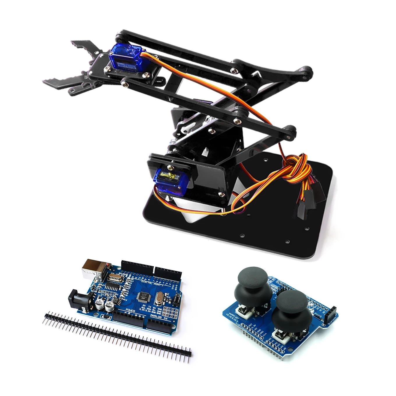
4-axis joystick controlling a 4-DOF acrylic robot arm with claw

Joystick Robot Arm: 4-Axis Control with PCA9685

Control a joystick robot arm with a 4-axis joystick and a PCA9685 servo driver. The joystick gives three analog axes, X tilt, Y tilt, and Z twist, plus a momentary button on top, which the listing counts as the fourth axis. X maps to base rotation, Y maps to the shoulder, and Z twist maps to the elbow.

Quick facts

Item Value
Arm 4-DOF acrylic arm kit with claw, 4 SG90 servos in the With SG90 option
Joystick 4-axis potentiometer, 10 k, X Y tilt plus Z twist, top button; 3 analog outputs plus the button
Driver PCA9685, 16 channels, I2C address 0x40
Controller Arduino Uno R3, 5 V logic
Joints Base, shoulder, elbow, plus claw; 4 servos, no wrist joint
Servo supply Separate 5 to 6 V, sized for stall current

Joystick robot arm: what does each joystick axis control?

The joystick gives three analog signals, one per potentiometer, plus the top button. The X tilt controls the base rotation, so pushing the stick left and right spins the arm around its vertical axis. The Y tilt controls the shoulder, so pushing forward and back raises and lowers the upper arm. The Z twist controls the elbow, so twisting the stick bends the forearm. There is no fourth analog output on this joystick: the fourth axis in the product name is the momentary top button, and this arm kit has no wrist joint, so no wrist mapping exists. The button toggles the claw instead.

That mapping is a choice, not a law. If the twist feels wrong for the elbow, swap the elbow and shoulder assignments in the code. The mapping lives in three lines, one per joint, so changing it takes a minute. Keep the mapping you choose written on a card next to the joystick until it becomes habit.

The top button toggles the claw. Press once and the claw closes, press again and it opens. A toggle suits a claw, because holding a button down while the arm moves is awkward. The sketch debounces the button with a 200 ms debounce interval, so one press never registers as two.

How do you map a joystick reading to a servo angle?

Each joystick axis is a 10 k potentiometer, so the Uno analog pin reads 0 to 1023. Center is near 512. The sketch reads the pin, subtracts the center, and applies a dead zone of about 30 counts so a resting stick sends no motion. Outside the dead zone, the reading maps to a small angle step per loop, not to an absolute angle.

Relative control suits an arm. The stick sets the speed and direction of each joint, and the joint holds its position when the stick centers. Absolute control, where the stick position equals the joint angle, is simpler to code but twitchy in practice, because a small stick move swings the joint a long way.

Each joint has a safe angle range in the sketch. The base runs 0 to 180 degrees, the shoulder 30 to 150 degrees, and the elbow 30 to 150 degrees. The claw runs 20 to 160 degrees. Those limits keep the arm from driving its own joints into the table or past the servo end stops. Adjust them for your arm after the first test, and write the final numbers down.

How do you wire the joystick and the PCA9685?

The joystick has three analog outputs, one per potentiometer, plus a button output. The X and Y potentiometers end in solder tabs on the sides of the base, so solder wires to them and meter each wire before you connect it. The Z potentiometer comes prewired: red and white are the reference ends and black is the wiper. Wire each potentiometer as a voltage divider across the 5 V supply and read the wiper on an ADC pin: X wiper to A0, Y wiper to A1, and Z wiper (black wire) to A2. The top button has two blue wires: connect one to digital pin 2 and the other to ground, and use INPUT_PULLUP, so a press reads LOW.

The PCA9685 connects over I2C. Connect its VCC to the Uno 5 V pin, its GND to ground, its SDA to A4, and its SCL to A5. Connect the separate 5 to 6 V servo supply to the V+ screw terminal, and join the supply ground to the Uno ground. The servo plugs go on channels 0 to 3: base, shoulder, elbow, and claw.

Keep the joystick wires short and away from the servo power wires. Servo current spikes can couple into long analog wires and make the joints jitter. If a joint trembles with the stick centered, widen the dead zone from 30 to 50 counts before you change anything else.

How do you tune the arm so it moves smoothly?

Start with slow steps. The sketch moves each joint by at most 1 degree per 20 ms loop, which is about 50 degrees per second at full stick deflection. That is fast enough to feel responsive and slow enough to stay controllable. Raise the step to 2 degrees only after the arm tracks well at 1 degree.

Load changes everything. An empty claw moves freely, but a loaded claw sags the shoulder and elbow servos. Test with the load you plan to lift, not empty. If the shoulder sags under load, raise the servo supply from 5 V to 6 V, which adds torque, or reduce the load. Do not raise the supply above the servo 6 V rating for SG90 servos.

If the arm oscillates, the steps are too large or the dead zone is too small. Lower the step size first. If one joint alone oscillates, check its pulse calibration, because a pulse past the servo end stop makes the servo fight its own gears and buzz.

Wiring

Wire the build with the power off. Check every connection in the table before you connect any battery or USB cable.

From To Notes
Joystick VCC Uno 5 V 10 k potentiometers, 5 V logic
Joystick GND Uno GND Common ground
Joystick X wiper Uno A0 Base rotation, analog 0 to 1023; solder tabs on the base, meter before soldering
Joystick Y wiper Uno A1 Shoulder, analog 0 to 1023; solder tabs on the base, meter before soldering
Joystick Z wiper, black wire Uno A2 Elbow, analog 0 to 1023; red and white are the reference ends
Joystick top button, blue wires Uno digital pin 2 and GND Claw toggle; INPUT_PULLUP, press reads LOW
PCA9685 VCC Uno 5 V Logic only, a few milliamps
PCA9685 GND Uno GND and servo supply negative Common ground for all three
PCA9685 SDA Uno A4 I2C data
PCA9685 SCL Uno A5 I2C clock
PCA9685 V+ screw terminal Separate 5 to 6 V supply positive Servo power only; size for stall current
PCA9685 channel 0 Base servo Signal, V+, GND
PCA9685 channel 1 Shoulder servo Signal, V+, GND
PCA9685 channel 2 Elbow servo Signal, V+, GND
PCA9685 channel 3 Claw servo Signal, V+, GND; toggled by the top button

Power budget

The logic side draws only a few milliamps from the Uno 5 V pin: the joystick potentiometers and the PCA9685 chip. The servo side draws whatever the servos demand. Four micro servos moving together draw on the order of 1 A under light load, and far more when they start or stall together.

Use a separate 5 to 6 V supply rated at 3 A or more for the V+ terminal. Never power the servos from the Uno 5 V pin. The Uno regulator supplies about 500 mA from USB, and a single stalled micro servo can exceed that. The board will reset and the arm will drop. No authoritative TowerPro datasheet publishes an SG90 stall current, so do not size the supply from a single stall number: the 3 A rating above is a planning rating with headroom, and meter your own servos if you need an exact figure.

Add a 470 to 1000 microfarad capacitor across V+ and ground at the terminal. The servos draw sharp spikes when they start moving, and the capacitor absorbs them. Without it, the rail sags and every joint jitters at once.

Build steps

  1. Assemble the 4-DOF acrylic arm kit with the claw. Fit the 4 SG90 servos and confirm each joint moves freely by hand before you power anything. Buy the With SG90 option: the Arm Only option ships as acrylic parts and screws with no servos.
  2. Mount the PCA9685 near the arm base. Connect the four servos to channels 0 to 3 in base, shoulder, elbow, and claw order.
  3. Wire the joystick to the Uno analog pins and the button to digital pin 2 from the wiring table.
  4. Wire the PCA9685 I2C pins and the separate servo supply. Join the supply ground to the Uno ground. Leave the servo supply off for now.
  5. Install the Adafruit PWM Servo Driver library. Upload the sketch below with the servo supply still off.
  6. Switch the servo supply on. The arm should park at its home position: base 90, shoulder 90, elbow 90, claw open.
  7. Push the stick in each direction and confirm the right joint moves. Press the top button and confirm the claw toggles. Calibrate the pulse limits per joint until no servo buzzes at its ends.

Code

Library: Adafruit PWM Servo Driver library. Board: Arduino Uno R3. Each joystick axis drives one joint in relative steps, and the top button toggles the claw. The joystick has three analog axes, so the claw is the only joint on the button; the kit has no wrist joint.

// Joystick robot arm: 4-axis joystick + PCA9685, 4 servos
// Board: Arduino Uno R3. Library: Adafruit PWM Servo Driver.
#include 
#include 

Adafruit_PWMServoDriver pwm = Adafruit_PWMServoDriver(0x40);

#define SERVOMIN 150   // About 730 microseconds at 50 Hz; calibrate per servo
#define SERVOMAX 600   // About 2930 microseconds at 50 Hz; calibrate per servo
#define SERVO_FREQ 50

const int JOY_X = A0;  // Base
const int JOY_Y = A1;  // Shoulder
const int JOY_Z = A2;  // Elbow
const int BTN_PIN = 2; // Claw toggle, INPUT_PULLUP

const uint8_t CH_BASE = 0, CH_SHOULDER = 1, CH_ELBOW = 2;
const uint8_t CH_CLAW = 3;

// Safe joint ranges in degrees. Adjust for your arm after testing.
const int LIM[4][2] = {{0, 180}, {30, 150}, {30, 150}, {20, 160}};
int angle[4] = {90, 90, 90, 20};  // Start parked, claw open
bool clawClosed = false;
unsigned long lastBtnMs = 0;

uint16_t angleToPulse(int a) {
  return map(constrain(a, 0, 180), 0, 180, SERVOMIN, SERVOMAX);
}

void setServo(uint8_t ch, int a) {
  pwm.setPWM(ch, 0, angleToPulse(a));
}

// Read one joystick axis and return a step of -1, 0, or +1.
int readStep(int pin) {
  int v = analogRead(pin) - 512;  // Center is near 512
  if (v > 30) return 1;           // Dead zone of 30 counts
  if (v < -30) return -1;
  return 0;
}

void moveJoint(uint8_t ch, int step) {
  if (step == 0) return;
  angle[ch] = constrain(angle[ch] + step, LIM[ch][0], LIM[ch][1]);
  setServo(ch, angle[ch]);
}

void setup() {
  Serial.begin(115200);
  pinMode(BTN_PIN, INPUT_PULLUP);
  pwm.begin();
  pwm.setOscillatorFrequency(27000000);
  pwm.setPWMFreq(SERVO_FREQ);
  delay(10);
  for (uint8_t ch = 0; ch < 4; ch++) setServo(ch, angle[ch]);
}

void loop() {
  moveJoint(CH_BASE, readStep(JOY_X));
  moveJoint(CH_SHOULDER, readStep(JOY_Y));
  moveJoint(CH_ELBOW, readStep(JOY_Z));

  // Top button toggles the claw, debounced by 200 ms.
  if (digitalRead(BTN_PIN) == LOW && millis() - lastBtnMs > 200) {
    lastBtnMs = millis();
    clawClosed = !clawClosed;
    angle[CH_CLAW] = clawClosed ? LIM[CH_CLAW][1] : LIM[CH_CLAW][0];
    setServo(CH_CLAW, angle[CH_CLAW]);
  }
  delay(20);  // About 1 degree per 20 ms at full deflection
}

Test and tune it

Center the stick and confirm all joints hold still. A joint that creeps with a centered stick has a joystick reading outside the dead zone. Widen the dead zone from 30 to 50 counts.

Move each joint to both ends of its range. A servo that buzzes at an end is past its mechanical limit. Lower the limit in the LIM table for that joint until the buzz stops.

Pick up a light object with the claw and hold it for 30 seconds. If the shoulder sags, raise the servo supply from 5 V to 6 V or reduce the load. Do not exceed the SG90 6 V rating.

FAQ

Which joystick axis controls which joint?

X controls the base, Y controls the shoulder, and Z twist controls the elbow. The top button toggles the claw. There is no fourth analog axis and no wrist joint on this kit: the fourth axis in the product name is the top button. Swap the assignments in the code if another mapping feels better.

Why does the arm jitter when the stick is centered?

The joystick reading sits outside the dead zone, or servo current spikes are coupling into the analog wires. Widen the dead zone to 50 counts and keep the joystick wires away from the servo power wires.

Why does the arm drop when I power it on?

The servos have no holding torque until the sketch parks them, and the Uno 5 V pin cannot hold them under load. Power the servos from the separate V+ supply and let the sketch park the arm at startup.

Can I use MG996R servos on this arm?

Only if the arm frame and the supply suit them. An MG996R draws up to 2.5 A at stall on 6 V, so four of them need a far larger supply than four SG90 servos. Check the arm kit servo mounts first.

How do I stop a joint from hitting the table?

Set its safe range in the LIM table in the sketch. The shoulder and elbow limits of 30 to 150 degrees keep the arm from driving its joints into the table or past the servo end stops.

Parts used

Build it with the 4-Axis Joystick Potentiometer with Momentary Top Button, 10K, X Y Tilt plus Z Twist, for Arduino, ESP32, and Robot Projects, the PCA9685 16-Channel PWM Servo Driver Board, 12-Bit IIC Interface, Arduino + Raspberry Pi, 2-Pack, and the 4-DOF Acrylic Robot Arm Kit with Claw for Arduino, Unassembled, SG90 / UNO / Rocker Options. For a servo arm build without the driver board, see How to Build a Robot Arm with ESP32 and Servo Motors, and the servo signal behind the positions is Digital vs Analog Servo Guide: Which Servo Holds Center.

Sources

Last updated: 2026-11-21. Search volume: not verified. Product links use the store short link form with the product ID; confirm the product slug at publish time.

Arduino UNO R3 Pinout: Digital, Analog, PWM, and Power

Push button wired to an Arduino input pin with a 10k pull-up resistor

Arduino UNO R3 Pinout: Digital, Analog, PWM, and Power

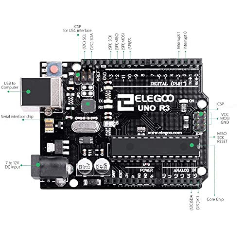
Answer in brief: The Arduino UNO R3 has 14 digital pins, 6 analog inputs, and 6 PWM pins. It runs on 5 volt logic at a 16 megahertz clock. This guide maps each pin, the power pins, and the current limits. It also covers I2C, SPI, UART, and the pins to avoid.

Quick Facts

Item Detail Source
Chip ATmega328P Arduino UNO R3 documentation
Clock speed 16 megahertz Arduino UNO R3 documentation
Logic voltage 5 volts Arduino UNO R3 documentation
Digital pins 14 pins, D0 to D13 Arduino UNO R3 documentation
PWM pins 6 pins: D3, D5, D6, D9, D10, D11 Arduino UNO R3 documentation
Analog inputs 6 inputs, A0 to A5, 10-bit Microchip ATmega328P datasheet DS40002061B
Analog range 0 counts to 1023 counts Microchip ATmega328P datasheet DS40002061B
Per-pin current, recommended 20 milliamperes Microchip ATmega328P datasheet DS40002061B
Per-pin current, absolute max 40 milliamperes Microchip ATmega328P datasheet DS40002061B
Chip total current 200 milliamperes Microchip ATmega328P datasheet DS40002061B
3V3 output, max About 50 milliamperes Arduino UNO R3 documentation
VIN range, recommended 7 volts to 12 volts Arduino UNO R3 documentation

Arduino UNO R3 Pinout Table

This table is an original pinout table built from the Arduino UNO R3 documentation. It is not a copied image. The D names are the printed header names on the board. Use the table with the board in front of you.

Pin Function Shared functions
D0 Digital I/O UART RX
D1 Digital I/O UART TX
D2 Digital I/O Interrupt INT0
D3 Digital I/O, PWM Interrupt INT1, PWM at 490 hertz
D4 Digital I/O None
D5 Digital I/O, PWM PWM at 980 hertz
D6 Digital I/O, PWM PWM at 980 hertz
D7 Digital I/O None
D8 Digital I/O None
D9 Digital I/O, PWM PWM at 490 hertz
D10 Digital I/O, PWM SPI SS, PWM at 490 hertz
D11 Digital I/O, PWM SPI MOSI, PWM at 490 hertz
D12 Digital I/O SPI MISO
D13 Digital I/O SPI SCK, onboard LED
A0 Analog input Digital pin D14
A1 Analog input Digital pin D15
A2 Analog input Digital pin D16
A3 Analog input Digital pin D17
A4 Analog input Digital pin D18, I2C SDA
A5 Analog input Digital pin D19, I2C SCL
VIN Power input 7 volts to 12 volts recommended
5V Power output 5 volt rail from USB or regulator
3V3 Power output 3.3 volt output, about 50 milliamperes max
GND Ground Common ground for all wiring
IOREF Reference Board logic voltage, 5 volts
AREF Reference Analog reference input
RESET Reset Pull low to restart the chip

Power Pins

Power the UNO R3 through USB, the barrel jack, or the VIN pin. The barrel jack and VIN accept 7 volts to 12 volts. The on-board regulator drops that input to 5 volts. A higher input makes the regulator run hotter. Keep the input near 9 volts for bench work when you can.

The 5V pin is a 5 volt output when USB or the jack powers the board. It can also act as a 5 volt input. Feed it only with a clean, regulated 5 volt supply. Do not feed it with a higher voltage. The 3V3 pin gives 3.3 volts at about 50 milliamperes max. Use it only for small 3.3 volt parts.

IOREF tells a shield the board logic voltage. On this board, IOREF is 5 volts. AREF sets the top of the analog range. Leave AREF unconnected for normal use. The default reference is 5 volts. Ground pins appear on both headers. Use the nearest ground for each part.

Boot and Reset Pins

The UNO R3 has no strapping pins like an ESP32 board. It starts code on power-up or reset. The RESET pin restarts the chip when pulled low. The on-board RESET button does the same job. A shield can also pull RESET low.

Uploads use the USB port and the on-board USB-to-serial chip. The IDE resets the board through the serial link. No jumper is needed for normal uploads. If an upload fails, press RESET once and try again. Check the board and port selection in the IDE first.

The ICSP header near the chip carries SPI and reset for direct programming. Most users never need it. Leave it alone unless you program the chip with an external programmer. A wrong ICSP connection can erase the bootloader.

ADC Pins

The UNO R3 has 6 analog inputs, A0 through A5. Each input reads 10-bit values from 0 counts to 1023 counts. A 0 volt input reads 0 counts. A 5 volt input reads 1023 counts. That step size is about 4.9 millivolts per count at the default reference.

A0 through A5 also work as digital pins D14 through D19. Use them as digital outputs when you run out of digital pins. Set the pin mode in code. A pin cannot read analog and drive digital at the same time.

PWM Pins

PWM is available on 6 pins: D3, D5, D6, D9, D10, and D11. The PWM frequency is 490 hertz on D3, D9, D10, and D11. It is 980 hertz on D5 and D6. That split matters for some loads. A motor driver may buzz at one frequency and run smooth at the other.

PWM drives a signal, not a load. Use a transistor or a driver for a motor. Use a series resistor for an LED. A PWM pin still follows the 20 milliampere recommended limit. Do not connect a motor directly to a PWM pin.

I2C Pins

I2C uses A4 for SDA and A5 for SCL. Those two analog pins carry the bus. Connect a display or a sensor to those two pins. Share the bus with more than one device when each device has a different address.

A4 and A5 cannot read analog while they run the I2C bus. Plan the pin budget when you need both I2C and analog reads. Use A0 through A3 for analog in that case. That leaves A4 and A5 free for the bus.

SPI Pins

SPI uses D10 for SS, D11 for MOSI, D12 for MISO, and D13 for SCK. Those four pins carry the bus. Pick a different digital pin for a second chip select when you add a second SPI device. D10 must stay an output for the board to act as SPI master.

SPI runs at 5 volt logic on this board. Check the device voltage before you connect it. A 3.3 volt SPI device needs a level shifter. A direct 5 volt connection can damage a 3.3 volt part.

UART Pins

UART uses D0 for RX and D1 for TX. Those pins connect to the USB-to-serial chip. They carry the serial monitor link. They also carry uploads. Do not connect a GPS module to D0 and D1 while you debug over USB. The two uses clash.

Keep the baud rate the same on both ends of a UART link. A mismatch gives garbled text. Start at 9600 baud for a new device. Raise the rate only after the link works.

USB Pins

The UNO R3 has a USB port for power and programming. The product in this guide uses a USB cable in the box. Check the product page for the cable type in your pack. The USB link powers the board at 5 volts. It also carries uploads and serial debug output.

The USB port does not expose D0 and D1 as separate pads. Those pins are the UART lines behind the USB chip. Treat D0 and D1 as busy during uploads. Free them only after the upload ends.

Pins to Avoid

Avoid D0 and D1 for sensors while you debug over USB. Avoid A4 and A5 for analog reads while I2C is active. Avoid D10 as a general input when SPI runs as master. It must stay an output in that mode.

Avoid AREF as a power output. It is a reference input only. Avoid feeding 5 volts into the 3V3 pin. Avoid feeding more than 5 volts into the 5V pin. Both mistakes can damage the regulator or the chip.

Avoid a load above 20 milliamperes on any single pin. Avoid a total load above 200 milliamperes across the chip. Those limits come from the Microchip ATmega328P datasheet DS40002061B. Stay under them for a long board life.

Max Current and Logic Voltage

Logic voltage is 5 volts on every digital pin. That value comes from the Arduino UNO R3 documentation. Treat 5 volts as the high level. Treat 0 volts as the low level. A 3.3 volt sensor output may read as high on a 5 volt input, but check the sensor datasheet first.

The recommended current per pin is 20 milliamperes. The absolute max per pin is 40 milliamperes. The chip total is 200 milliamperes. Those three numbers come from the Microchip ATmega328P datasheet DS40002061B. Treat 20 milliamperes as the working limit. Treat 40 milliamperes as a damage threshold, not a target.

The 3V3 output gives about 50 milliamperes max. That value comes from the Arduino UNO R3 documentation. Use it only for small 3.3 volt parts. A WiFi module or a large display needs its own regulator.

Wiring and Power Warnings

Power the board before you connect a sensor. Keep the USB cable short. Use a cable under 3 feet for bench tests when you can. Long wires pick up noise. Noise causes analog jitter and I2C errors.

Use a series resistor for every LED. A 220 ohm resistor is a common bench value for a 5 volt LED test. Check the LED datasheet for its own forward voltage before you pick a resistor. A LED with no resistor can draw too much current from the pin.

Use a driver for any motor, relay, or solenoid. The GPIO pin only signals the driver. The driver handles the load current. A direct motor connection can damage the pin and reset the board.

Pin Test Sketch

Language: Arduino. Library: Arduino AVR core version 1.8.6, with no extra library install. Code status: code not compiled. No arduino-cli or PlatformIO is installed in this environment.

// Arduino UNO R3 pin test sketch
// Board: UNO R3, ATmega328P
// Arduino AVR core version 1.8.6
// Code status: code not compiled

// PWM test pin is D9. It runs at 490 hertz.
const int pwmPin = 9;
// Analog test pin is A0. It reads 0 to 1023 counts.
const int analogPin = A0;
// Onboard LED pin is D13.
const int ledPin = 13;

void setup() {
  // Start serial at 9600 baud for debug output.
  Serial.begin(9600);
  delay(500); // Wait 500 milliseconds for the monitor.

  // Set the PWM pin and the LED pin as outputs.
  pinMode(pwmPin, OUTPUT);
  pinMode(ledPin, OUTPUT);

  Serial.println("UNO R3 pin test started");
}

void loop() {
  // Read the analog value on A0.
  int adcValue = analogRead(analogPin);
  Serial.print("A0 value: ");
  Serial.println(adcValue);

  // Fade the PWM output on D9 from off to full.
  for (int level = 0; level <= 255; level += 5) {
    analogWrite(pwmPin, level);
    delay(20); // Wait 20 milliseconds per step.
  }

  // Blink the onboard LED on D13 once per loop.
  digitalWrite(ledPin, HIGH);
  delay(500); // Wait 500 milliseconds.
  digitalWrite(ledPin, LOW);
  delay(500); // Wait 500 milliseconds.
}

Expected result: the serial monitor shows an A0 value each loop. The value changes with the voltage on A0. The PWM output on D9 fades up in steps. The onboard LED blinks once per loop. If no serial output appears, check the board and port selection in the IDE.

Frequently Asked Questions

How many digital pins does the UNO R3 have?

It has 14 digital pins, D0 through D13. Six of those pins support PWM. The analog pins A0 through A5 can also work as digital pins D14 through D19.

Which pins are PWM on the UNO R3?

PWM pins are D3, D5, D6, D9, D10, and D11. D5 and D6 run at 980 hertz. The other four PWM pins run at 490 hertz.

What is the current limit per pin?

The recommended limit is 20 milliamperes per pin. The absolute max is 40 milliamperes per pin. The chip total is 200 milliamperes. Stay under the recommended limit for normal use.

Can I power the UNO R3 from the VIN pin?

Yes, feed VIN with 7 volts to 12 volts. The on-board regulator drops that input to 5 volts. Keep the input near 9 volts for bench work. A higher input makes the regulator run hotter.

Boards That Match This Pinout

These boards use the pinout in this guide. Check the product page for current stock before you order. Stock changes over time.

Related reading: compare this board with other microcontroller families in the staged pillar RP2040 vs ESP32 (row 24, staged). For a first project, see the live post How to Start with a UNO R3 Board for Arduino Projects (live post #15177) and the live post How to Build Your First Arduino Project with UNO and OLED (live post #15203). For sibling pinouts, see Nano V3.0 USB-C Guide: ATmega328P Board for Arduino IDE and Raspberry Pi Pico Pinout.

Sources

  • Arduino UNO R3 documentation, https://docs.arduino.cc/hardware/uno-rev3/
  • Microchip ATmega328P datasheet DS40002061B, https://ww1.microchip.com/downloads/en/DeviceDoc/Atmel-7810-Automotive-Microcontrollers-ATmega328P_Datasheet.pdf
  • Arduino UNO R3 schematic, https://docs.arduino.cc/hardware/uno-rev3/

Last updated 2026-11-21.