
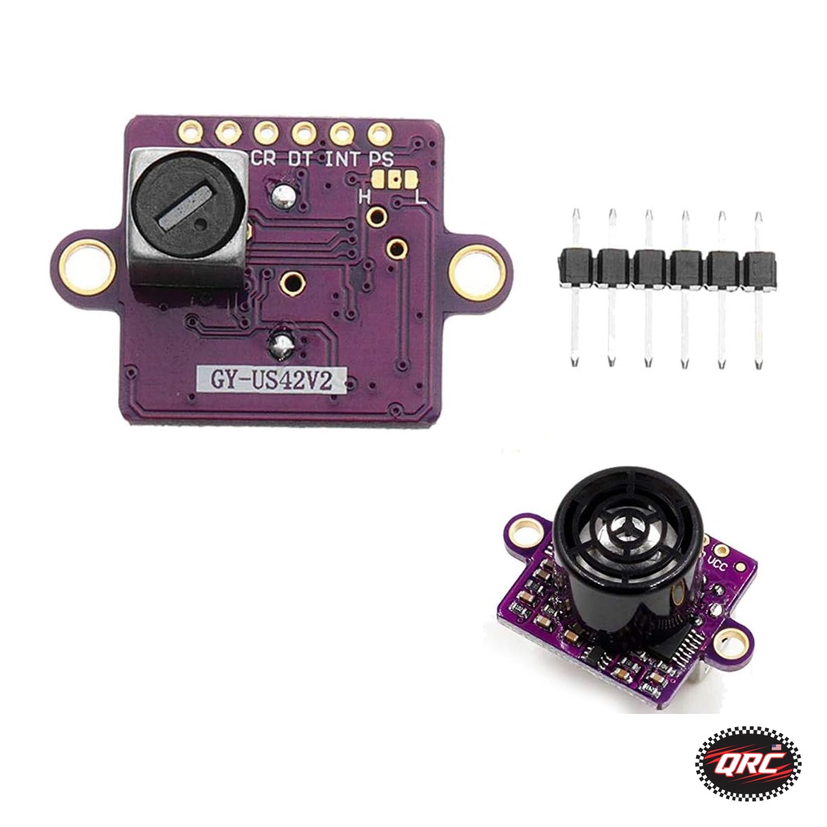
GY-US42 I2C Ultrasonic Distance Sensor with Arduino
The GY-US42 gives you distance over I2C, and that one fact changes how you wire it. An HC-SR04 needs two pins and a timed pulse for every reading. The GY-US42 sits on the I2C bus with your other sensors, takes one command, and returns the distance as a number. This guide wires it to an Arduino, reads distance over I2C, and covers the UART and PWM modes for when I2C is not the right call.
The module in the store is the HiLetgo GY-US42 Ultrasonic Distance Sensor Module, I2C UART PWM, for Pixhawk and APM Flight Controllers ($17.99). It runs on 3 to 5V, reads over UART at TTL level, I2C, or pulse PWM output in the same style as the SR04, and the listing notes it replaces the MB1242 and SRF02. The serial baud rate is configurable at 9600 or 115200 bps with continuous or on-request output, settings are saved, and the I2C address can be changed so several modules share one bus.
Quick facts
| Fact | Value |
|---|---|
| Module | GY-US42 (GY-US42V2 board marking), 1 module |
| Supply | 3 to 5V |
| Interfaces | I2C, UART TTL, PWM pulse output |
| Serial baud | 9600 or 115200 bps, configurable, settings saved |
| Output modes | Continuous or on-request |
| I2C address | Changeable, so several modules share one bus |
| Replaces | MB1242, SRF02 |
| Good for | Altitude hold, landing checks, obstacle sensing, robot ranging |
Wiring for I2C
I2C is the mode to start with. Four wires, and the module joins the same bus as your display or other I2C sensors. On a Nano or Uno, SDA is A4 and SCL is A5. On an ESP32 DevKit, the default I2C pins are GPIO 21 for SDA and GPIO 22 for SCL.
| GY-US42 pin | Arduino Nano / Uno | ESP32 DevKit |
|---|---|---|
| VCC | 5V | 5V (module runs 3 to 5V) |
| GND | GND | GND |
| SDA | A4 | GPIO 21 |
| SCL | A5 | GPIO 22 |
The board for this guide can be the Nano V3.0 Development Board, ATmega328P, CH340G, USB-C, Single ($8.49) or the ESP32 DevKit V1 Development Board, 30-Pin WROOM-32, WiFi + Bluetooth, Dual-Core ($13.99). On the ESP32, the module runs on 3.3V logic without level shifting, since the module supply range covers 3 to 5V. On a 5V Nano, the I2C lines run at the module supply you choose; if you power the module from 5V, keep the bus at 5V as the module expects. See the sensor wiring guide for ESP32, Arduino, and Pico and the logic level shifting guide before mixing 5V and 3.3V parts on one bus.
Arduino code: read distance over I2C
The GY-US42 follows the SRF02 command set, which the listing names as the module it replaces. Send command 0x51 to register 0x00 to start a ranging in centimeters, wait about 100 ms, then read two bytes from register 0x01. The first byte is the high byte, the second is the low byte.
#include <Wire.h>

#define GY_US42_ADDR 0x70

void setup() {
  Serial.begin(9600);
  Wire.begin();
}

int readDistanceCM() {
  Wire.beginTransmission(GY_US42_ADDR);
  Wire.write(0x00);
  Wire.write(0x51);
  Wire.endTransmission();
  delay(100);
  Wire.beginTransmission(GY_US42_ADDR);
  Wire.write(0x01);
  Wire.endTransmission();
  Wire.requestFrom(GY_US42_ADDR, 2);
  if (Wire.available() < 2) {
    return -1;
  }
  int dist = (Wire.read() << 8) | Wire.read();
  return dist;
}

void loop() {
  int dist = readDistanceCM();
  if (dist < 0) {
    Serial.println("No reading");
  } else {
    Serial.print("Distance: ");
    Serial.print(dist);
    Serial.println(" cm");
  }
  delay(500);
}
Open the serial monitor at 9600 baud. Point the sensor at a flat wall about a meter away and you should see steady readings within a centimeter or two. Move a book closer and the numbers should track it with no lag you can notice.
UART and PWM modes
I2C is the cleanest mode, but it is not the only one. UART mode talks at TTL level at 9600 or 115200 bps, with continuous or on-request output, and the setting is saved on the module. Use UART when the sensor is far from the board or when the I2C bus is already full. PWM mode outputs a pulse in the same style as the SR04: measure the pulse width and convert it to distance. Use PWM when you want the simplest possible read on one digital pin and you do not need the bus.
One practical note: the I2C address can be changed, so two GY-US42 modules can share one bus, one on each side of a robot. That is the mode to use for a robot that needs left and right ranging without a multiplexer. Change the address on one module first, with the other module unplugged, so you do not re-address both at once.
GY-US42 vs HC-SR04 vs VL53L0X
The HC-SR04 Ultrasonic Distance Sensor with Bracket, 2-Pack ($11.99) is the cheapest way to get a distance reading, and it is the right pick for a first robot or a simple parking sensor. It needs two pins and a timed pulse, and it shares nothing with your other sensors. The GY-US42 costs more but joins the I2C bus, which matters when the board is already running a display, a compass, and a temperature sensor on the same two wires.
The VL53L0X Time-of-Flight Laser Distance Sensor Breakout, 2M Range ($4.99) is a different technology: a laser time-of-flight sensor, not ultrasound. It reads small targets at short range with a narrow beam, while the ultrasonic modules read wider areas at longer range and work on soft targets the laser can miss. For altitude hold and landing checks, ultrasound is the safer pick. For a small robot that needs to know exactly how far the wall in front of it is, the laser wins. See the VL53L0X time-of-flight guide for the laser side of that choice.
Compatibility and limits
The GY-US42 works with Arduino, ESP32, ESP8266, and Raspberry Pi, and it is built for Pixhawk and APM flight controllers for altitude sensing. It reads distance from an ultrasonic pulse and echo, so soft surfaces like cloth, foam, and angled walls can absorb or deflect the pulse and read long or not at all. That is normal for every ultrasonic sensor, not a fault in this module. Flat, hard surfaces facing the sensor read cleanly. The module is a small low-power range sensor, so keep the sensing face clear and do not mount it behind a grill or a cover that blocks the sound path.
Troubleshooting
If the sketch prints “No reading” every time, check the wiring first: SDA to A4 and SCL to A5 on a Nano or Uno, and the right I2C pins on an ESP32. Run an I2C scanner sketch to confirm the module answers at its address. If the scanner finds nothing, check power: the module needs 3 to 5V, and a loose ground wire is the most common cause.
If readings jump around, the target is the problem, not the code. A narrow pole, a slanted wall, or a soft curtain will scatter the echo. Test against a flat wall first, then move to the real target. If readings freeze at one value, something else on the bus may be holding SDA or SCL low; unplug the other I2C devices and test the GY-US42 alone.
If two modules return the same reading, they are on the same address. Change one module’s address with the other unplugged, then plug both in and scan the bus to confirm two addresses answer.
Frequently asked questions
Does the GY-US42 work with a 5V Arduino?
Yes. The module runs on 3 to 5V, so a 5V Nano or Uno powers it directly. Wire SDA to A4 and SCL to A5, and use the sketch above.
Does it work with an ESP32?
Yes. Power it from 3.3V or 5V, wire SDA to GPIO 21 and SCL to GPIO 22, and the same I2C sketch works. The module supply range covers both.
Can I use two GY-US42 modules on one Arduino?
Yes, because the I2C address can be changed. Set one module to a different address with the other unplugged, then run both on the same bus and read each by its own address.
What is the difference between I2C, UART, and PWM on this module?
I2C shares the bus with other sensors and returns a number on request. UART sends distance as serial text at 9600 or 115200 bps. PWM outputs a pulse whose width matches the distance, like an HC-SR04. Pick I2C for a multi-sensor build, UART for a long cable run, PWM for a single-pin read.
Why does it read wrong on soft or angled surfaces?
Ultrasound reflects off hard, flat surfaces and absorbs or scatters off soft or angled ones. A curtain, a foam block, or a wall at a sharp angle can read long or return nothing. Test against a flat wall to confirm the module, then aim it squarely at the real target.
Is the GY-US42 better than an HC-SR04?
It is better when you need I2C, a changeable address, or a module that also talks UART and PWM. The HC-SR04 is cheaper and simpler for a single sensor on a first build. Pick the GY-US42 when the bus matters, the HC-SR04 when the price matters.
Parts for this build
Shipped fast and securely from our secure facility in New York, providing fast, high quality USA shipping.
HiLetgo GY-US42 Ultrasonic Distance Sensor Module, I2C UART PWM, for Pixhawk and APM Flight Controllers ($17.99)
The sensor for this guide. I2C, UART, and PWM output, 3 to 5V, changeable I2C address, and it replaces the MB1242 and SRF02.
HC-SR04 Ultrasonic Distance Sensor with Bracket, 2-Pack ($11.99)
The budget alternative for a single-sensor build. Two pins, timed pulse, and a bracket in the box.
VL53L0X Time-of-Flight Laser Distance Sensor Breakout, 2M Range ($4.99)
The laser alternative when you need a narrow beam and short-range precision instead of ultrasound.
ESP32 DevKit V1 Development Board, 30-Pin WROOM-32, WiFi + Bluetooth, Dual-Core ($13.99)
The board for a WiFi-connected distance build. Default I2C pins are GPIO 21 and GPIO 22.
Related guides
- Sensor Wiring for ESP32, Arduino, and Pico: I2C, SPI, UART, and Analog Checks
- How to Build an Ultrasonic Distance Meter with HC-SR04
- VL53L0X Time of Flight Distance Sensor for Robots: Range, Wiring, and VL53L1X Comparison
- Logic Level Shifting 5V to 3.3V: Safe Wiring for ESP32, Arduino, Sensors, and Displays