
Hexapod Spider Robot Kit Build: 18 Servos, Six Legs
Build the hexapod spider robot kit with 18 servos across six legs, driven by PCA9685 boards over I2C. Three legs lift and swing while the other three hold the body up, which is the tripod gait. The servos need a 5 to 6 V supply rated at 10 A, because 18 servos can draw more than any USB port supplies.
Quick facts
| Item | Value |
|---|---|
| Legs | 6 legs, 3 servos per leg, 18 servos total |
| Gait | Tripod gait: 3 legs lift, 3 legs support |
| Drivers | PCA9685 boards, 16 channels each; two boards cover 18 servos |
| Controller | Freenove Crawling Robot Controller in the kit, Arduino IDE compatible; wireless remote included |
| Servo supply | Separate 5 to 6 V, sized for stall current |
| Battery | Not included; 2x 3.7 V 18650 flat-top cells plus a charger, bought separately |
Hexapod spider robot kit: how does it walk?
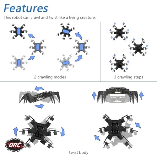
A hexapod walks with a tripod gait. At any moment, three legs touch the ground and hold the body up, while the other three lift, swing forward, and set down. Then the two tripods swap. The body never has fewer than three legs on the ground, so it stays stable without balancing.
Each leg has three servos: a hip servo that swings the leg forward and back, a knee servo that lifts the leg, and an ankle servo that sets the foot angle. Three servos per leg times six legs is 18 servos. No Arduino has 18 PWM pins to spare, which is why the build uses PCA9685 boards.
The two tripods are the front left, middle right, and rear left legs in one group, and the front right, middle left, and rear right legs in the other. Lift one tripod, swing it forward, set it down, then lift the other. That is the whole walk. Turning shifts the swing direction, and strafing shifts the foot targets sideways.
Why do 18 servos need two PCA9685 boards?
One PCA9685 drives 16 servos. Eighteen servos need two boards, with 16 channels on the first and 2 on the second. The boards share one I2C bus, so the wiring stays at two wires plus power. Set the first board to address 0x40 and the second to 0x41 with its A0 solder pad, then pass each address to its own library object.
Both boards share the same 50 Hz servo frequency, and each channel is independent. The sketch below creates two driver objects, one per address, and a helper that maps a servo number from 0 to 17 onto the right board and channel. The gait code then thinks in legs and joints, not in boards and channels.
The kit as shipped needs no PCA9685 at all: its own Freenove Crawling Robot Controller drives all 18 servos directly from ports 22 to 39, with the yellow servo wire to S, red to +, and black to -. The kit ships with a remote, and the kit controller plus its provided library handle the first walks. The PCA9685 wiring in this post is the path for builders who drive the servos from their own board instead of the kit controller. The kit tutorial also requires the batteries to be fully charged before assembly, with about 8.0 to 8.4 V across the two 18650 cells, and warns that wrong batteries can damage the servos.
How do you size power for 18 servos?
Size for stall current, not idle current. Eighteen servos starting or stalling together draw several amps, far more than any USB port or board regulator supplies. No single authoritative figure exists for the stall current of the servos in this kit, and the common SG90 stall figures disagree across resellers, so this post states no per-servo current number. Size generously and meter the rail on your own build.
Use a separate 5 to 6 V supply rated at 10 A or more for the servo rail, and feed it to the PCA9685 V+ terminals. A 5 V 10 A bench supply works on the bench. That 10 A rating is a planning rating with headroom, not a computed stall total. The kit itself runs from 2x 3.7 V 18650 cells, which is a separate power path from the PCA9685 servo rail in this post; do not feed the 18650 pack straight into the servo rail.
Add a large capacitor across each V+ terminal, 1000 microfarads or more, close to the board. Eighteen servos starting at once draw a sharp spike, and the capacitor absorbs it. Use thick wire for the V+ feed, because thin jumper wires drop voltage at 10 A and heat up. Never route servo current through the Arduino 5 V pin.
How do you assemble and test the legs?
Assemble one leg at a time and test it before you fit the next. Center each servo at 90 degrees with the sketch before you fit the horn, so the leg starts at its middle position. A horn fitted 30 degrees off center steals a third of that joint travel and the leg will never reach its full step.
Test the tripod gait with the body held up in your hand first. Lift the robot, run the gait, and watch the feet. Three feet should lift and swing while the other three stay still, then swap. If a leg swings the wrong way, its hip servo is reversed in the mapping, so flip its direction sign in the code, not the wiring.
Set the robot down only after the lifted test looks right. On the floor, start with short steps and low speed. A hexapod that steps too far tips forward, because the support tripod moves behind the center of mass. Short steps keep the body over its feet.
Wiring
Wire the build with the power off. Check every connection in the table before you connect any battery or USB cable.
| From | To | Notes |
|---|---|---|
| PCA9685 board 1 VCC | Controller 5 V or 3V3 | Logic only; use 3.3 V on an ESP32 so the I2C pull-ups stay at 3.3 V |
| PCA9685 board 1 GND | Controller GND and servo supply negative | Common ground for all three |
| PCA9685 board 1 SDA | Controller SDA | I2C data; address 0x40, A0 pad open |
| PCA9685 board 1 SCL | Controller SCL | I2C clock |
| PCA9685 board 2 VCC | Controller 5 V or 3V3 | Logic only |
| PCA9685 board 2 GND | Controller GND and servo supply negative | Common ground |
| PCA9685 board 2 SDA | Controller SDA | Shared I2C bus; address 0x41, A0 pad bridged |
| PCA9685 board 2 SCL | Controller SCL | Shared I2C bus |
| Both boards V+ terminals | Separate 5 to 6 V supply, 10 A or more | Servo power only; thick wire, one feed per board |
| Board 1 channels 0 to 15 | Servos 0 to 15 | Legs 1 to 5 full sets plus one joint of leg 6 |
| Board 2 channels 0 and 1 | Servos 16 and 17 | Remaining two joints of leg 6 |
| Capacitor 1000 uF or more | Across each V+ terminal and ground | Absorbs the 18-servo start-up spike; mind the polarity |
Power budget
Eighteen micro servos draw several amps while walking and far more if they all stall at once, so the supply must cover the walking current with margin, and the fuse or pack must survive the stall spike without cutting out mid-step. A 5 V 10 A bench supply is the bench choice. A battery pack needs the same current rating. The kit battery is 2x 3.7 V 18650 flat-top cells plus a charger, none of which are included.
The logic side draws only a few milliamps. The controller, the two PCA9685 chips, and the remote receiver run from the controller supply. The servo rail is separate, and only the grounds join. Never power the servos from the controller 5 V pin, and never feed the servo supply into the controller.
Heat matters at 10 A. Use thick wire for the V+ feeds, keep the runs short, and check the terminal screws after the first hour of walking. A loose screw at 10 A heats up and drops voltage, and the legs will jitter and stall.
Build steps
- Unbox the kit and count the parts: frame, six legs, 18 servos, horns, screws, the Freenove Crawling Robot Controller, and remote. Confirm the battery is not included: buy 2x 3.7 V 18650 flat-top cells plus a charger, and fully charge them before assembly.
- Run the kit as shipped first if you can: load the provided code on the kit controller, calibrate the servos with the calibration graph in the kit tutorial, and walk it on the remote. The PCA9685 steps below are the own-board alternative, not the kit default.
- Center every servo at 90 degrees with the sketch before you fit any horn. Fit each horn at the middle position.
- Assemble one leg at a time: hip, knee, then ankle. Test each leg by hand for free movement before you fit the next.
- Fit the six legs to the body in the tripod groups: front left, middle right, rear left in one group, and the other three in the second group.
- Wire the two PCA9685 boards from the wiring table. Set board 1 to 0x40 and board 2 to 0x41 with the A0 pad.
- Connect the servos to the boards in order, 0 to 17, and connect the separate servo supply to both V+ terminals. Join the grounds.
- Upload the sketch below. Hold the body up and run the tripod gait. Confirm three legs lift and swing while the other three hold still, then swap.
- Set the robot on the floor and walk it forward in short steps. Shorten the step if it tips forward.
Code
Library: Adafruit PWM Servo Driver library. Board: Arduino IDE compatible controller. The sketch maps servo numbers 0 to 17 across two PCA9685 boards and runs a basic tripod gait. Tune the step size and the per-leg direction signs for your kit.
// Hexapod spider robot: 18 servos, 2 x PCA9685, tripod gait
// Board: Arduino IDE compatible controller.
// Library: Adafruit PWM Servo Driver (Adafruit_PWMServoDriver).
#include
#include

Adafruit_PWMServoDriver pwmA = Adafruit_PWMServoDriver(0x40);  // Servos 0-15
Adafruit_PWMServoDriver pwmB = Adafruit_PWMServoDriver(0x41);  // Servos 16-17

#define SERVOMIN 150   // About 730 microseconds at 50 Hz; calibrate per servo
#define SERVOMAX 600   // About 2930 microseconds at 50 Hz; calibrate per servo
#define SERVO_FREQ 50

// Legs 0-5, joints 0=hip, 1=knee, 2=ankle. Servo number = leg*3 + joint.
// Tripod 1: legs 0, 2, 4. Tripod 2: legs 1, 3, 5.
const uint8_t TRIPOD1[3] = {0, 2, 4};
const uint8_t TRIPOD2[3] = {1, 3, 5};

uint16_t angleToPulse(int angle) {
  return map(constrain(angle, 0, 180), 0, 180, SERVOMIN, SERVOMAX);
}

void setServo(uint8_t servo, int angle) {
  uint16_t pulse = angleToPulse(angle);
  if (servo < 16) pwmA.setPWM(servo, 0, pulse);
  else pwmB.setPWM(servo - 16, 0, pulse);
}

void setLeg(uint8_t leg, int hip, int knee, int ankle) {
  setServo(leg * 3 + 0, hip);
  setServo(leg * 3 + 1, knee);
  setServo(leg * 3 + 2, ankle);
}

void setTripod(const uint8_t legs[3], int hip, int knee, int ankle) {
  for (uint8_t i = 0; i < 3; i++) setLeg(legs[i], hip, knee, ankle);
}

void setup() {
  pwmA.begin();
  pwmA.setOscillatorFrequency(27000000);
  pwmA.setPWMFreq(SERVO_FREQ);
  pwmB.begin();
  pwmB.setOscillatorFrequency(27000000);
  pwmB.setPWMFreq(SERVO_FREQ);
  delay(10);
  // Park every servo at 90 degrees: legs centered, feet down.
  for (uint8_t s = 0; s < 18; s++) setServo(s, 90);
  delay(500);
}

void loop() {
  // Tripod gait, one step per cycle. Tune the angles for your kit.
  // Lift tripod 1, swing forward, set down.
  setTripod(TRIPOD1, 110, 60, 90);  // Lift and swing forward
  delay(300);
  setTripod(TRIPOD1, 110, 90, 90);  // Set down
  setTripod(TRIPOD2, 70, 90, 90);   // Push body forward
  delay(300);
  // Lift tripod 2, swing forward, set down.
  setTripod(TRIPOD2, 110, 60, 90);
  delay(300);
  setTripod(TRIPOD2, 110, 90, 90);
  setTripod(TRIPOD1, 70, 90, 90);
  delay(300);
}
Test and tune it
Hold the body up and run the gait. Three legs should lift and swing while the other three stay still, then swap. If a leg in the wrong tripod moves, its leg number is wrong in the TRIPOD table.
If a leg swings backward instead of forward, flip its hip direction sign in the gait code. Do not rewire the servo, because the mapping is the fault.
Set the robot down and walk it 3 feet. If it tips forward, shorten the swing from 110 degrees toward 100 degrees. Short steps keep the body over the support tripod.
FAQ
How many servos does a hexapod need?
Eighteen servos: three per leg times six legs. Each leg has a hip servo, a knee servo, and an ankle servo. One PCA9685 drives 16 servos, so this build uses two boards.
What is the tripod gait?
Three legs hold the body up while the other three lift, swing forward, and set down. Then the two tripods swap. The body always has three legs on the ground, so it stays stable without balancing.
Why does my hexapod jitter when it walks?
The servo supply sags under the start-up spike of 18 servos. Add a 1000 microfarad capacitor across each V+ terminal, check the supply current rating, and tighten the terminal screws.
Can I power 18 servos from USB?
No. Eighteen micro servos together draw several amps while walking and far more at stall. Use a separate 5 to 6 V supply rated at 10 A or more for the servo rail.
Does the kit include a battery?
No. The kit needs 2x 3.7 V 18650 flat-top cells plus a charger, none included, and the remote takes 1x 9 V battery or USB power. For the PCA9685 servo rail in this post, use a bench supply for indoor testing.
Parts used
Build it with the Hexapod Spider Robot Kit with Remote, Six Legs with 18 Motors, Arduino IDE Compatible, Walking and Crawling STEM Project (Battery Not Included) and the PCA9685 16-Channel PWM Servo Driver Board, 12-Bit IIC Interface, Arduino + Raspberry Pi, 2-Pack (two boards cover 18 servos; one board drives only 16). For a servo arm build without the driver board, see How to Build a Robot Arm with ESP32 and Servo Motors, and the arm build uses the same driver in Joystick Robot Arm: 4-Axis Control with PCA9685. For the servo signal behind the positions, see Digital vs Analog Servo Guide: Which Servo Holds Center.
Sources
- Adafruit 16-Channel PWM Servo Driver guide
- Adafruit PCA9685 guide PDF
- Freenove Hexapod Robot Kit FNK0031 tutorial, Assembly
Last updated: 2026-11-21. Search volume: not verified. Product links use the store short link form with the product ID; confirm the product slug at publish time.