How Stepper Motors Work: Steps, Coils, and Microstepping

NEMA 17 stepper motor beside a 28BYJ-48 stepper motor and A4988 driver

How Stepper Motors Work: Steps, Coils, and Microstepping

A stepper motor turns in fixed steps instead of spinning freely. A standard NEMA 17 motor has a step angle of 1.8 degrees, so it takes exactly 200 steps to turn one full revolution. Each pulse from the driver moves the rotor one step, so counting pulses tells you exactly how far the shaft has turned, with no encoder.

How stepper motors work: what is a stepper motor?

A stepper motor is a brushless DC motor that divides a full rotation into a fixed number of equal steps. Inside the motor, a stator carries coil windings and a rotor carries a permanent magnet or a toothed iron assembly. When current flows through a pair of stator coils, the magnetic field pulls the rotor into line with the energised coils. When the driver energises the next pair of coils in sequence, the rotor moves one step further round. Keep the coils energised and the motor holds its position firmly, with no brake needed.

A standard NEMA 17 motor has 50 rotor teeth and 4 magnetic field orientations from its two phases, which gives 50 times 4, or 200 steps per revolution. Divide 360 degrees by 200 steps and the step angle is 1.8 degrees. A 0.9 degree motor has 400 steps per revolution and gives finer resolution at the cost of less torque per step.

NEMA 17 describes the mounting face, not the motor performance. NEMA 17 means a 1.7 inch square face, or 42.3 mm square. Two NEMA 17 motors can have very different lengths, torques and currents. Always read the current rating and the holding torque of your exact motor, not just the NEMA size.

How does a stepper differ from a DC motor and a servo?

A DC motor spins freely when power is applied, and its speed depends on voltage and load. It has no built in position, so a robot that needs to know how far a wheel turned must add an encoder. A servo moves to a commanded angle and holds it with a closed loop, but its range is usually limited to 180 degrees. A stepper moves in fixed steps over unlimited rotations, and the step count is the position, so it needs no encoder for open loop positioning.

Spec (unit) DC motor Servo Stepper motor
Motion Continuous rotation Limited angle, usually 180 degrees Fixed steps, unlimited rotation
Position feedback None, add encoder Built in potentiometer None, step count is position
Typical control PWM duty for speed PWM pulse width for angle STEP pulses for distance
Holding torque at rest None without power Holds angle under load Holds position with coils energised
Best for Wheels, fans, pumps Steering, arms, pan tilt 3D printers, CNC, precise positioning

The trade off is speed and efficiency. A stepper draws full current even when it holds still, so it runs hotter and uses more power than a DC motor at rest. A stepper also loses steps when the load exceeds its torque, and because there is no feedback, the controller never knows the steps were lost. Size the motor and the driver for the load with margin, and never trust a stepper position after a stall.

What are unipolar and bipolar steppers?

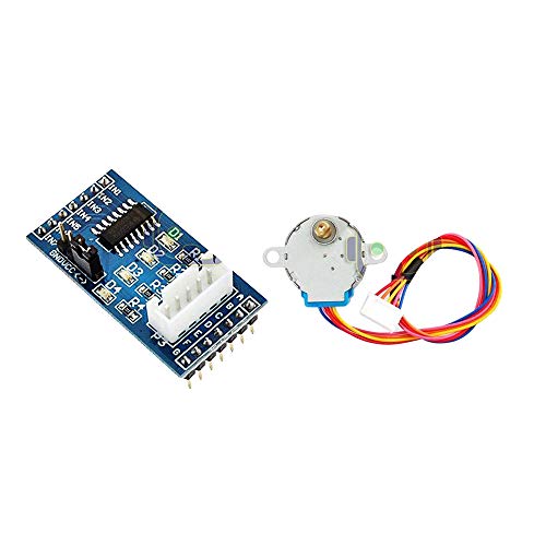
A unipolar stepper has four coils with centre taps, and it is driven by energising one half of each coil at a time. It has five or six wires, and it is simple to drive with a transistor array such as the ULN2003. The 28BYJ-48 is the common unipolar example: a small 5 V geared stepper with a ULN2003 driver board. Unipolar drive is simple, but it uses only half of each coil at a time, so it gives less torque per size than a bipolar motor.

A bipolar stepper has two coils and four wires, with no centre taps. It is driven by an H-bridge that reverses the current through the full coil, which gives 30 to 40 percent more torque than a unipolar motor of the same size. The NEMA 17 is the common bipolar example, and it needs a bipolar driver such as the A4988 or the TMC2208. Bipolar drive is more complex, but it is the standard for 3D printers and CNC machines, where torque matters.

Identify your motor by its wire count before you buy a driver. Five or six wires means unipolar, and a ULN2003 board is the pick. Four wires means bipolar, and an A4988 board is the pick. A four wire motor on a ULN2003 board does not work, and a five wire motor on an A4988 board does not work either.

How does microstepping work?

Microstepping divides each full step into smaller increments by driving the two coils with different currents at the same time. Instead of switching one coil fully on and the other fully off, the driver sets the two coil currents to intermediate values that hold the rotor between two full step positions. The A4988 supports five resolutions, set by its MS1, MS2 and MS3 pins: full step, 1/2 step, 1/4 step, 1/8 step and 1/16 step.

MS1 MS2 MS3 Resolution Steps per revolution (count)
LOW LOW LOW Full step 200
HIGH LOW LOW 1/2 step 400
LOW HIGH LOW 1/4 step 800
HIGH HIGH LOW 1/8 step 1600
HIGH HIGH HIGH 1/16 step 3200

Microstepping makes motion smoother and quieter, and it reduces resonance at low speeds. It does not increase accuracy by the same factor as the step count, because the intermediate positions depend on the exact coil currents and the load. A 1/16 microstep is finer than a full step, but the holding torque at a microstep is lower than at a full step, and the rotor position at a microstep is less exact under load. Use microstepping for smooth motion, not for a promise of 16 times the precision.

How does the 28BYJ-48 work?

The 28BYJ-48 is a geared unipolar stepper. The inner motor takes 32 full steps per turn, at 11.25 degrees per full step, and a gear train of about 64:1 sits behind it, so the output shaft needs about 2,048 steps for one full turn, from 32 times 64. The datasheet ratio is 64:1, so 2,048 is the nominal figure. Teardown counts of the gear teeth give an exact ratio of 63.68395:1, or 283712/4455, on the units counted, which works out to 2037.9 full steps, or 4075.8 half steps, per output turn. The ratio varies by manufacturer, and some units are a true 64:1, so use 2,048 as the nominal value. Over many turns, the small error adds up, so do not use the 28BYJ-48 for long distance odometry without a home sensor.

The 28BYJ-48 runs on 5 V and it is easy to drive with its ULN2003 board, which takes four logic inputs, IN1 to IN4, from the microcontroller. It is slow, under about 15 RPM, and light on torque, but it is ideal for learning, for clocks, for curtain pullers and for a pan tilt head that moves slowly. The standard Arduino Stepper library drives it with 2,048 steps per revolution, and the pin order matters: the sequence 8, 10, 9, 11 is correct for the common wiring, and 8, 9, 10, 11 makes the motor twitch instead of turning.

How does the A4988 driver work?

The A4988, datasheet 4988-DS Rev. 8, April 5, 2022, is a microstepping driver IC from Allegro MicroSystems for bipolar steppers. It drives motors at up to 2 A per coil with proper cooling, and it supports up to 1/16 microstepping. From the microcontroller it needs only two signal pins: STEP, where one pulse advances the motor one microstep, and DIR, where high or low selects the direction. The EN pin enables or disables the driver, and the MS1 to MS3 pins set the microstep resolution.

Setting the current limit correctly is the most important A4988 job. The driver has a small potentiometer that sets Vref, and the current limit follows the formula Vref equals current times 8 times Rsense. Set Vref to about 80 percent of your motor rated current, fit the heatsink, and never power the board with the motor disconnected, because the driver can fail permanently. The motor supply, VMOT, runs from 8 V to 35 V, and a 100 uF capacitor across VMOT close to the board absorbs current spikes.

The A4988 is the standard driver for a NEMA 17 in a 3D printer or a CNC axis. The TMC2208 is the quieter successor, with StealthChop silent operation, but the A4988 is cheaper and its current setting procedure is the one every tutorial covers.

How do you pick a stepper for a project?

Project type Pick this motor Why
Learning, slow pan tilt, clock 28BYJ-48 plus ULN2003 5 V, simple wiring, cheap, 2,048 steps per turn
3D printer axis, CNC axis NEMA 17 plus A4988 200 steps per turn, 1/16 microstepping, high holding torque
Quiet printer axis NEMA 17 plus TMC2208 StealthChop silent stepping, same 200 step motor
Precise positioning, no feedback NEMA 17, 0.9 degree version 400 steps per turn, finer resolution than 1.8 degree

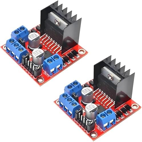
For the drivers behind the motor signals, see L298N vs TB6612 vs DRV8833: Which Motor Driver for Your Robot.

FAQ

How many steps does a NEMA 17 take per revolution?

200 steps at full step, because its step angle is 1.8 degrees and 360 divided by 1.8 is 200. At 1/16 microstepping, it takes 3,200 microsteps per revolution.

Why does my stepper lose steps?

The load exceeds the motor torque, the speed is too high for the torque curve, or the driver current limit is set too low. Reduce the speed, raise the current limit within the motor rating, or use a larger motor.

Can I drive a stepper directly from a GPIO pin?

No. A stepper coil draws far more current than a GPIO pin supplies. Always use a driver board, such as a ULN2003 for a unipolar motor or an A4988 for a bipolar motor, between the pins and the motor.

Does microstepping increase torque?

No. Microstepping makes motion smoother and quieter, but the holding torque at a microstep is lower than at a full step. Use it for smooth motion, not for more torque.

What is the difference between unipolar and bipolar?

A unipolar motor has centre tapped coils and five or six wires, and it is driven by a ULN2003. A bipolar motor has two coils and four wires, and it is driven by an H-bridge such as the A4988. Bipolar gives more torque per size.

Parts used

28BYJ-48 Stepper Motor 5V plus ULN2003 Driver, 2-Set: the geared unipolar stepper for learning and slow positioning. A4988 Stepper Motor Driver: the bipolar microstepping driver for NEMA 17 motors. Nema 17 Stepper Motor: the bipolar stepper for 3D printer and CNC axes.

Sources

Last updated: 2026-11-21. Search volume: not verified. Product links use the store short link form with the product ID; confirm the product slug at publish time.
Hexapod Spider Robot Kit Build: 18 Servos, Six Legs

Hexapod spider robot kit with six legs and 18 servos

Hexapod Spider Robot Kit Build: 18 Servos, Six Legs

Build the hexapod spider robot kit with 18 servos across six legs, driven by PCA9685 boards over I2C. Three legs lift and swing while the other three hold the body up, which is the tripod gait. The servos need a 5 to 6 V supply rated at 10 A, because 18 servos can draw more than any USB port supplies.

Quick facts

Item Value
Legs 6 legs, 3 servos per leg, 18 servos total
Gait Tripod gait: 3 legs lift, 3 legs support
Drivers PCA9685 boards, 16 channels each; two boards cover 18 servos
Controller Freenove Crawling Robot Controller in the kit, Arduino IDE compatible; wireless remote included
Servo supply Separate 5 to 6 V, sized for stall current
Battery Not included; 2x 3.7 V 18650 flat-top cells plus a charger, bought separately

Hexapod spider robot kit: how does it walk?

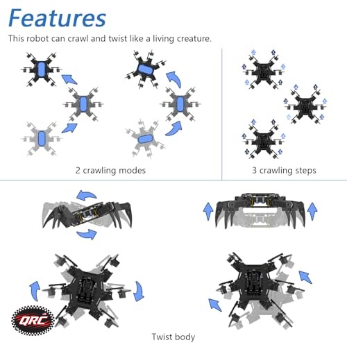
A hexapod walks with a tripod gait. At any moment, three legs touch the ground and hold the body up, while the other three lift, swing forward, and set down. Then the two tripods swap. The body never has fewer than three legs on the ground, so it stays stable without balancing.

Each leg has three servos: a hip servo that swings the leg forward and back, a knee servo that lifts the leg, and an ankle servo that sets the foot angle. Three servos per leg times six legs is 18 servos. No Arduino has 18 PWM pins to spare, which is why the build uses PCA9685 boards.

The two tripods are the front left, middle right, and rear left legs in one group, and the front right, middle left, and rear right legs in the other. Lift one tripod, swing it forward, set it down, then lift the other. That is the whole walk. Turning shifts the swing direction, and strafing shifts the foot targets sideways.

Why do 18 servos need two PCA9685 boards?

One PCA9685 drives 16 servos. Eighteen servos need two boards, with 16 channels on the first and 2 on the second. The boards share one I2C bus, so the wiring stays at two wires plus power. Set the first board to address 0x40 and the second to 0x41 with its A0 solder pad, then pass each address to its own library object.

Both boards share the same 50 Hz servo frequency, and each channel is independent. The sketch below creates two driver objects, one per address, and a helper that maps a servo number from 0 to 17 onto the right board and channel. The gait code then thinks in legs and joints, not in boards and channels.

The kit as shipped needs no PCA9685 at all: its own Freenove Crawling Robot Controller drives all 18 servos directly from ports 22 to 39, with the yellow servo wire to S, red to +, and black to -. The kit ships with a remote, and the kit controller plus its provided library handle the first walks. The PCA9685 wiring in this post is the path for builders who drive the servos from their own board instead of the kit controller. The kit tutorial also requires the batteries to be fully charged before assembly, with about 8.0 to 8.4 V across the two 18650 cells, and warns that wrong batteries can damage the servos.

How do you size power for 18 servos?

Size for stall current, not idle current. Eighteen servos starting or stalling together draw several amps, far more than any USB port or board regulator supplies. No single authoritative figure exists for the stall current of the servos in this kit, and the common SG90 stall figures disagree across resellers, so this post states no per-servo current number. Size generously and meter the rail on your own build.

Use a separate 5 to 6 V supply rated at 10 A or more for the servo rail, and feed it to the PCA9685 V+ terminals. A 5 V 10 A bench supply works on the bench. That 10 A rating is a planning rating with headroom, not a computed stall total. The kit itself runs from 2x 3.7 V 18650 cells, which is a separate power path from the PCA9685 servo rail in this post; do not feed the 18650 pack straight into the servo rail.

Add a large capacitor across each V+ terminal, 1000 microfarads or more, close to the board. Eighteen servos starting at once draw a sharp spike, and the capacitor absorbs it. Use thick wire for the V+ feed, because thin jumper wires drop voltage at 10 A and heat up. Never route servo current through the Arduino 5 V pin.

How do you assemble and test the legs?

Assemble one leg at a time and test it before you fit the next. Center each servo at 90 degrees with the sketch before you fit the horn, so the leg starts at its middle position. A horn fitted 30 degrees off center steals a third of that joint travel and the leg will never reach its full step.

Test the tripod gait with the body held up in your hand first. Lift the robot, run the gait, and watch the feet. Three feet should lift and swing while the other three stay still, then swap. If a leg swings the wrong way, its hip servo is reversed in the mapping, so flip its direction sign in the code, not the wiring.

Set the robot down only after the lifted test looks right. On the floor, start with short steps and low speed. A hexapod that steps too far tips forward, because the support tripod moves behind the center of mass. Short steps keep the body over its feet.

Wiring

Wire the build with the power off. Check every connection in the table before you connect any battery or USB cable.

From To Notes
PCA9685 board 1 VCC Controller 5 V or 3V3 Logic only; use 3.3 V on an ESP32 so the I2C pull-ups stay at 3.3 V
PCA9685 board 1 GND Controller GND and servo supply negative Common ground for all three
PCA9685 board 1 SDA Controller SDA I2C data; address 0x40, A0 pad open
PCA9685 board 1 SCL Controller SCL I2C clock
PCA9685 board 2 VCC Controller 5 V or 3V3 Logic only
PCA9685 board 2 GND Controller GND and servo supply negative Common ground
PCA9685 board 2 SDA Controller SDA Shared I2C bus; address 0x41, A0 pad bridged
PCA9685 board 2 SCL Controller SCL Shared I2C bus
Both boards V+ terminals Separate 5 to 6 V supply, 10 A or more Servo power only; thick wire, one feed per board
Board 1 channels 0 to 15 Servos 0 to 15 Legs 1 to 5 full sets plus one joint of leg 6
Board 2 channels 0 and 1 Servos 16 and 17 Remaining two joints of leg 6
Capacitor 1000 uF or more Across each V+ terminal and ground Absorbs the 18-servo start-up spike; mind the polarity

Power budget

Eighteen micro servos draw several amps while walking and far more if they all stall at once, so the supply must cover the walking current with margin, and the fuse or pack must survive the stall spike without cutting out mid-step. A 5 V 10 A bench supply is the bench choice. A battery pack needs the same current rating. The kit battery is 2x 3.7 V 18650 flat-top cells plus a charger, none of which are included.

The logic side draws only a few milliamps. The controller, the two PCA9685 chips, and the remote receiver run from the controller supply. The servo rail is separate, and only the grounds join. Never power the servos from the controller 5 V pin, and never feed the servo supply into the controller.

Heat matters at 10 A. Use thick wire for the V+ feeds, keep the runs short, and check the terminal screws after the first hour of walking. A loose screw at 10 A heats up and drops voltage, and the legs will jitter and stall.

Build steps

  1. Unbox the kit and count the parts: frame, six legs, 18 servos, horns, screws, the Freenove Crawling Robot Controller, and remote. Confirm the battery is not included: buy 2x 3.7 V 18650 flat-top cells plus a charger, and fully charge them before assembly.
  2. Run the kit as shipped first if you can: load the provided code on the kit controller, calibrate the servos with the calibration graph in the kit tutorial, and walk it on the remote. The PCA9685 steps below are the own-board alternative, not the kit default.
  3. Center every servo at 90 degrees with the sketch before you fit any horn. Fit each horn at the middle position.
  4. Assemble one leg at a time: hip, knee, then ankle. Test each leg by hand for free movement before you fit the next.
  5. Fit the six legs to the body in the tripod groups: front left, middle right, rear left in one group, and the other three in the second group.
  6. Wire the two PCA9685 boards from the wiring table. Set board 1 to 0x40 and board 2 to 0x41 with the A0 pad.
  7. Connect the servos to the boards in order, 0 to 17, and connect the separate servo supply to both V+ terminals. Join the grounds.
  8. Upload the sketch below. Hold the body up and run the tripod gait. Confirm three legs lift and swing while the other three hold still, then swap.
  9. Set the robot on the floor and walk it forward in short steps. Shorten the step if it tips forward.

Code

Library: Adafruit PWM Servo Driver library. Board: Arduino IDE compatible controller. The sketch maps servo numbers 0 to 17 across two PCA9685 boards and runs a basic tripod gait. Tune the step size and the per-leg direction signs for your kit.

// Hexapod spider robot: 18 servos, 2 x PCA9685, tripod gait
// Board: Arduino IDE compatible controller.
// Library: Adafruit PWM Servo Driver (Adafruit_PWMServoDriver).
#include 
#include 

Adafruit_PWMServoDriver pwmA = Adafruit_PWMServoDriver(0x40);  // Servos 0-15
Adafruit_PWMServoDriver pwmB = Adafruit_PWMServoDriver(0x41);  // Servos 16-17

#define SERVOMIN 150   // About 730 microseconds at 50 Hz; calibrate per servo
#define SERVOMAX 600   // About 2930 microseconds at 50 Hz; calibrate per servo
#define SERVO_FREQ 50

// Legs 0-5, joints 0=hip, 1=knee, 2=ankle. Servo number = leg*3 + joint.
// Tripod 1: legs 0, 2, 4. Tripod 2: legs 1, 3, 5.
const uint8_t TRIPOD1[3] = {0, 2, 4};
const uint8_t TRIPOD2[3] = {1, 3, 5};

uint16_t angleToPulse(int angle) {
  return map(constrain(angle, 0, 180), 0, 180, SERVOMIN, SERVOMAX);
}

void setServo(uint8_t servo, int angle) {
  uint16_t pulse = angleToPulse(angle);
  if (servo < 16) pwmA.setPWM(servo, 0, pulse);
  else pwmB.setPWM(servo - 16, 0, pulse);
}

void setLeg(uint8_t leg, int hip, int knee, int ankle) {
  setServo(leg * 3 + 0, hip);
  setServo(leg * 3 + 1, knee);
  setServo(leg * 3 + 2, ankle);
}

void setTripod(const uint8_t legs[3], int hip, int knee, int ankle) {
  for (uint8_t i = 0; i < 3; i++) setLeg(legs[i], hip, knee, ankle);
}

void setup() {
  pwmA.begin();
  pwmA.setOscillatorFrequency(27000000);
  pwmA.setPWMFreq(SERVO_FREQ);
  pwmB.begin();
  pwmB.setOscillatorFrequency(27000000);
  pwmB.setPWMFreq(SERVO_FREQ);
  delay(10);
  // Park every servo at 90 degrees: legs centered, feet down.
  for (uint8_t s = 0; s < 18; s++) setServo(s, 90);
  delay(500);
}

void loop() {
  // Tripod gait, one step per cycle. Tune the angles for your kit.
  // Lift tripod 1, swing forward, set down.
  setTripod(TRIPOD1, 110, 60, 90);  // Lift and swing forward
  delay(300);
  setTripod(TRIPOD1, 110, 90, 90);  // Set down
  setTripod(TRIPOD2, 70, 90, 90);   // Push body forward
  delay(300);
  // Lift tripod 2, swing forward, set down.
  setTripod(TRIPOD2, 110, 60, 90);
  delay(300);
  setTripod(TRIPOD2, 110, 90, 90);
  setTripod(TRIPOD1, 70, 90, 90);
  delay(300);
}

Test and tune it

Hold the body up and run the gait. Three legs should lift and swing while the other three stay still, then swap. If a leg in the wrong tripod moves, its leg number is wrong in the TRIPOD table.

If a leg swings backward instead of forward, flip its hip direction sign in the gait code. Do not rewire the servo, because the mapping is the fault.

Set the robot down and walk it 3 feet. If it tips forward, shorten the swing from 110 degrees toward 100 degrees. Short steps keep the body over the support tripod.

FAQ

How many servos does a hexapod need?

Eighteen servos: three per leg times six legs. Each leg has a hip servo, a knee servo, and an ankle servo. One PCA9685 drives 16 servos, so this build uses two boards.

What is the tripod gait?

Three legs hold the body up while the other three lift, swing forward, and set down. Then the two tripods swap. The body always has three legs on the ground, so it stays stable without balancing.

Why does my hexapod jitter when it walks?

The servo supply sags under the start-up spike of 18 servos. Add a 1000 microfarad capacitor across each V+ terminal, check the supply current rating, and tighten the terminal screws.

Can I power 18 servos from USB?

No. Eighteen micro servos together draw several amps while walking and far more at stall. Use a separate 5 to 6 V supply rated at 10 A or more for the servo rail.

Does the kit include a battery?

No. The kit needs 2x 3.7 V 18650 flat-top cells plus a charger, none included, and the remote takes 1x 9 V battery or USB power. For the PCA9685 servo rail in this post, use a bench supply for indoor testing.

Parts used

Build it with the Hexapod Spider Robot Kit with Remote, Six Legs with 18 Motors, Arduino IDE Compatible, Walking and Crawling STEM Project (Battery Not Included) and the PCA9685 16-Channel PWM Servo Driver Board, 12-Bit IIC Interface, Arduino + Raspberry Pi, 2-Pack (two boards cover 18 servos; one board drives only 16). For a servo arm build without the driver board, see How to Build a Robot Arm with ESP32 and Servo Motors, and the arm build uses the same driver in Joystick Robot Arm: 4-Axis Control with PCA9685. For the servo signal behind the positions, see Digital vs Analog Servo Guide: Which Servo Holds Center.

Sources

Last updated: 2026-11-21. Search volume: not verified. Product links use the store short link form with the product ID; confirm the product slug at publish time.
Mecanum Wheel Robot Car Build: Omni-Directional Drive

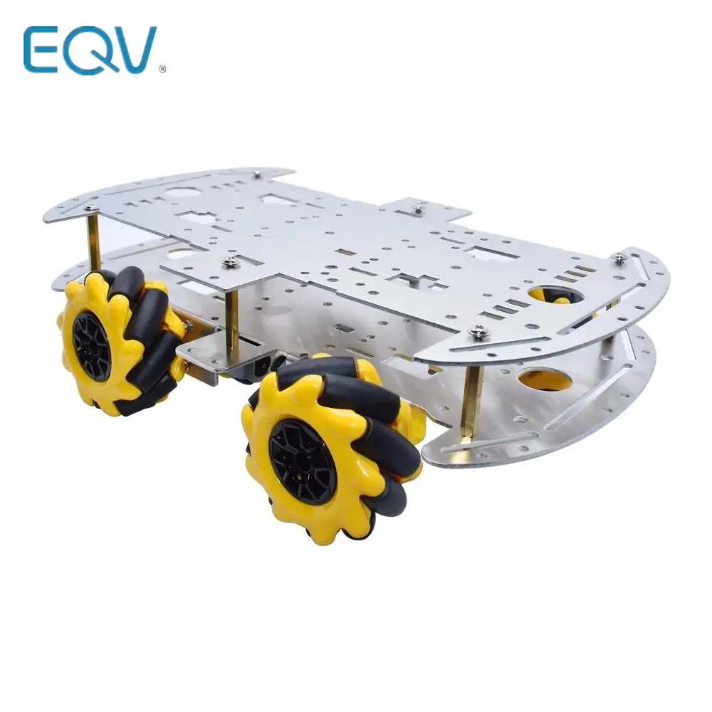
Mecanum wheel robot car chassis with four omni wheels

Mecanum Wheel Robot Car Build: Omni-Directional Drive

Build a mecanum wheel robot car that drives forward, sideways, and diagonally without turning. Each wheel carries rollers set at 45 degrees, and the four wheels spin in matched patterns to strafe. The build uses two L298N drivers, one per wheel pair, because one L298N drives only two motors and a mecanum car has four.

Quick facts

Item Value
Chassis Mecanum 4WD chassis, aluminum alloy, 0.20 feet omni wheels
Drivers 2 x L298N, one per wheel pair
Motors 4 x TT gear motors, 3 to 6 V
Controller ESP32 DevKit V1, 3.3 V logic
Roller angle 45 degrees on each wheel
Moves Forward, back, strafe left, strafe right, rotate, diagonal

Mecanum wheel robot car: how does a wheel move sideways?

A mecanum wheel has small rollers around its rim, each set at 45 degrees to the wheel axle. When the wheel spins, the roller pushes the car partly forward and partly sideways. One wheel alone would slide diagonally, but four wheels in the right pattern cancel the unwanted parts.

For a strafe left, the front left and rear right wheels spin one way while the front right and rear left spin the other way. The forward parts cancel and the sideways parts add. The car slides left without turning. Reverse the pattern and it strafes right. That is the move a normal car cannot make.

Wheel orientation matters. The rollers on the front left and rear right wheels must angle one way, and the rollers on the front right and rear left must angle the other way, forming an X pattern when viewed from above. If one wheel is fitted backward, the car will crab and spin instead of strafing. Check the X before you wire anything.

Why does this build need two L298N drivers?

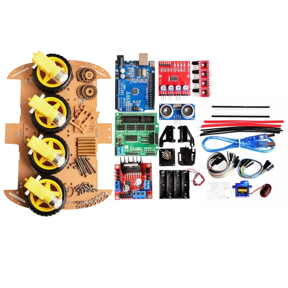
One L298N drives two DC motors. A mecanum car has four motors, so it needs two L298N modules. Each module drives one diagonal pair: the first drives the front left and rear right wheels, and the second drives the front right and rear left wheels. That pairing matches the strafe pattern and keeps the wiring tidy. Buy the 4WD Kit variant of the chassis kit: it ships with 4 TT gear motors and one L298N, so buy one more L298N for the second pair. The Plate Set variants ship with plates and wheels only, no motors or electronics. The 4WD Kit also includes a UNO R3 board and sensor shield; this build uses an ESP32 DevKit V1 in its place.

Each L298N needs its own enable and direction pins, so the build uses 12 control pins on the ESP32. The ESP32 DevKit V1 has enough GPIO pins for that, but a small board such as a SuperMini would not. Check the pinout post for your exact board before you substitute it.

Both L298N modules share one motor battery. Join the battery positive to both 12 V terminals and the battery negative to both grounds and to the ESP32 ground. Keep the 5 V jumper on at 6 V, and remove it above 12 V, on both modules.

How does the drive mix work?

The drive mix takes three inputs: forward speed, strafe speed, and rotation speed. Each wheel speed is a sum of those three with signs that depend on the wheel position. Front left equals forward plus strafe plus rotation. Front right equals forward minus strafe minus rotation. Rear left equals forward minus strafe plus rotation. Rear right equals forward plus strafe minus rotation.

The sketch below implements that mix for serial control. Type f for forward, s for strafe left, d for strafe right, l to rotate left, r to rotate right, and x to stop. Each key sets the four wheel speeds from the mix, clamps them to -255 to 255, and writes them to the two L298N modules.

Test the mix with the car lifted. Strafe left should spin the front left and rear right wheels one way and the other two the opposite way. If one wheel spins the wrong way, swap its two motor wires at its L298N output. Do not fix wheel direction in code, because the wiring is the fault.

What are the limits of a mecanum car?

Mecanum wheels slip more than normal wheels, because the rollers are always partly sliding. The car will not climb as well, will not push as hard, and will drift on smooth floors. It also draws more current, because two wheels fight each other in every strafe. Expect shorter battery life than a normal 4WD car on the same pack.

The rollers also wear faster than a solid tire, and they pick up grit. Keep the floor clean and the rollers free. A stuck roller turns a mecanum wheel into a bad normal wheel, and the car will crab instead of strafing.

For all that, the strafe is worth it on a bench or a small course. A mecanum car can slide sideways into a gap a normal car cannot reach, and it can rotate in place without a turning circle. That is why warehouse robots and camera dollies use the same wheel.

Wiring

Wire the build with the power off. Check every connection in the table before you connect any battery or USB cable.

From To Notes
Battery box positive Both L298N 12 V terminals Motor supply, 6 V from 4 AA cells
Battery box negative Both L298N GND and ESP32 GND Common ground for both drivers and the logic
L298N A OUT1, OUT2 Front left TT motor First module, left channel
L298N A OUT3, OUT4 Rear right TT motor First module, right channel
L298N B OUT1, OUT2 Front right TT motor Second module, left channel
L298N B OUT3, OUT4 Rear left TT motor Second module, right channel
ESP32 GPIO 25, 27, 14 L298N A ENA, IN1, IN2 Front left motor: PWM, direction A, direction B
ESP32 GPIO 26, 12, 13 L298N A ENB, IN3, IN4 Rear right motor: PWM, direction A, direction B; GPIO 12 is a strapping pin, keep low at boot
ESP32 GPIO 32, 33, 15 L298N B ENA, IN1, IN2 Front right motor: PWM, direction A, direction B
ESP32 GPIO 18, 19, 21 L298N B ENB, IN3, IN4 Rear left motor: PWM, direction A, direction B; GPIO 21 is also I2C SDA, so do not add I2C parts to this build
Both L298N 5 V pins Leave unconnected Jumpers fitted at 6 V; do not feed 5 V in as well
USB 5 V ESP32 USB port Logic supply only; motor current never passes through USB

Power budget

Four TT motors draw more than two. At full load the four motors together draw about 2 to 4 A from the 6 V pack, split across two L298N modules at about 1 to 2 A per module. Each L298N drops about 2 V, so each motor sees about 4 V. The heatsinks on both modules will get warm, so give them airflow.

The ESP32 runs from USB 5 V and draws about 80 to 160 mA. Each L298N logic side draws only a few milliamps from its onboard regulator. The motor battery and the logic supply share only a ground wire. Never power the motors from the ESP32 5 V pin.

A 4 AA alkaline pack sags under a 4 A load, so the car will slow during a strafe. A 5-cell NiMH pack (6 V) holds voltage better than alkalines under load. Do not use a 2-cell lithium pack here: 7.4 V nominal is above the TT motor 3 to 6 V rating. Size the pack for the stall total, not the cruise current.

Build steps

  1. Assemble the mecanum chassis. Fit the four wheels in the X roller pattern: front left and rear right angle one way, front right and rear left the other way.
  2. Mount the two L298N modules and the ESP32 on the top plate. Label the modules A and B before you wire them.
  3. Wire the motors to the L298N outputs from the wiring table. Wire both modules to the same battery and to the ESP32 ground.
  4. Remove all four enable jumpers. Wire the 12 control pins from the wiring table.
  5. Upload the sketch below to the ESP32 DevKit V1. Lift the car off the floor for the first test.
  6. Type f, s, d, l, and r in the serial monitor and confirm each wheel spins the right way for each move.
  7. Set the car on the floor and strafe left and right. If it crabs instead of strafing, one wheel is fitted backward or wired in reverse.

Code

Libraries: none beyond the ESP32 Arduino core. Board: ESP32 DevKit V1. Control from the serial monitor: f forward, b back, s strafe left, d strafe right, l rotate left, r rotate right, x stop.

// Mecanum wheel robot car: 4 motors, 2 x L298N, ESP32
// Board: ESP32 DevKit V1. No extra libraries needed.
// Module A drives front-left (FL) and rear-right (RR).
// Module B drives front-right (FR) and rear-left (RL).
struct MotorPins { int pwm, inA, inB; };
MotorPins FL = {25, 27, 14};  // Module A, channel 1
MotorPins RR = {26, 12, 13};  // Module A, channel 2
MotorPins FR = {32, 33, 15};  // Module B, channel 1
MotorPins RL = {18, 19, 21};  // Module B, channel 2

const int SPEED = 200;  // 0 to 255; TT motors stall below about 80

void driveMotor(MotorPins m, int speed) {
  if (speed >= 0) {
    digitalWrite(m.inA, HIGH);
    digitalWrite(m.inB, LOW);
    analogWrite(m.pwm, speed);
  } else {
    digitalWrite(m.inA, LOW);
    digitalWrite(m.inB, HIGH);
    analogWrite(m.pwm, -speed);
  }
}

void stopAll() {
  driveMotor(FL, 0); driveMotor(FR, 0);
  driveMotor(RL, 0); driveMotor(RR, 0);
}

// Mix: forward, strafe (right is positive), rotation (right is positive).
void mix(int fwd, int strafe, int rot) {
  int fl = constrain(fwd + strafe + rot, -255, 255);
  int fr = constrain(fwd - strafe - rot, -255, 255);
  int rl = constrain(fwd - strafe + rot, -255, 255);
  int rr = constrain(fwd + strafe - rot, -255, 255);
  driveMotor(FL, fl); driveMotor(FR, fr);
  driveMotor(RL, rl); driveMotor(RR, rr);
}

void setup() {
  Serial.begin(115200);
  MotorPins all[4] = {FL, FR, RL, RR};
  for (int i = 0; i < 4; i++) {
    pinMode(all[i].pwm, OUTPUT);
    pinMode(all[i].inA, OUTPUT);
    pinMode(all[i].inB, OUTPUT);
  }
  stopAll();
  Serial.println("Keys: f forward, b back, s strafe left, d strafe right,");
  Serial.println("l rotate left, r rotate right, x stop.");
}

void loop() {
  if (Serial.available() > 0) {
    char c = Serial.read();
    if (c == 'f') mix(SPEED, 0, 0);
    else if (c == 'b') mix(-SPEED, 0, 0);
    else if (c == 's') mix(0, -SPEED, 0);  // Strafe left
    else if (c == 'd') mix(0, SPEED, 0);   // Strafe right
    else if (c == 'l') mix(0, 0, -SPEED);  // Rotate left
    else if (c == 'r') mix(0, 0, SPEED);   // Rotate right
    else if (c == 'x') stopAll();
  }
}

Test and tune it

Lift the car and type s for strafe left. The front left and rear right wheels should spin one way, and the front right and rear left the opposite way. If one wheel is wrong, swap its two motor wires at its L298N output.

Set the car on a hard floor and strafe left 1 foot. The car should slide sideways without turning. If it rotates while strafing, one wheel is fitted backward. Check the X roller pattern from above.

Drive forward 3 feet and mark the end point. Then strafe back to the start. A mecanum car drifts more than a normal car, so expect about 0.25 feet of error. That drift is normal roller slip, not a code fault.

FAQ

Why does my mecanum car need two L298N drivers?

One L298N drives two motors, and a mecanum car has four. Two modules drive one diagonal pair each, which matches the strafe pattern and keeps the wiring tidy.

Why does my mecanum car crab instead of strafing?

One wheel is fitted backward or wired in reverse. Check the X roller pattern from above, then check that each wheel spins the right way for a strafe while the car is lifted.

Why does the car drift sideways when driving forward?

Mecanum rollers always slip a little, and uneven floors make it worse. Small drift is normal. Large drift means one wheel is slower, usually from a loose motor wire or a low battery.

Can I use one driver board with four channels instead?

Yes, if it supplies four independent channels at the motor current. Two L298N modules are the stocked route in this build. A single four-channel MOSFET board is a later upgrade, not a first build change.

How fast can a mecanum car strafe?

Slower than it drives forward, because two wheels fight each other in every strafe and the rollers slip. Keep strafe speed at or below forward speed, and expect shorter battery life than a normal 4WD car.

Parts used

Build it with the Mecanum Wheel 4WD Robot Car Chassis Kit, Aluminum Alloy, 60mm Omni Wheels in the 4WD Kit variant (Single or Double Layer) and one more L298N Dual H-Bridge Motor Driver Module for Arduino (the kit already includes one L298N; one L298N drives two motors, so a four-motor car needs two) and the ESP32 DevKit V1 Development Board, 30-Pin WROOM-32 as the controller. The two-motor version is L298N Robot Car: Wire and Drive Two DC Motors, and the wireless version is ESP-NOW Joystick Robot Car: Two ESP32 Boards, No Router. For the driver comparison, see L298N vs TB6612 vs DRV8833: Which Motor Driver for Your Robot.

Sources

Last updated: 2026-11-21. Search volume: not verified. Product links use the store short link form with the product ID; confirm the product slug at publish time.
Bluetooth Robot Car with ESP32 BLE and a Phone

Phone showing a BLE control app next to an ESP32 robot car

Bluetooth Robot Car with ESP32 BLE and a Phone

Control this Bluetooth robot car from your phone with the ESP32 native Bluetooth Low Energy radio. No HC-05 or HC-06 module is needed, because the ESP32 DevKit V1 already has BLE built in. The car runs a BLE server with one writable characteristic, the phone writes drive commands to it, and the car stops by itself when the phone disconnects.

Quick facts

Item Value
Radio ESP32 native BLE 4.2, no extra module
Control app nRF Connect or any BLE scanner app, free
Service One custom service, one writable drive characteristic
Commands Single letters: F, B, L, R, S, plus speed digits 0 to 9
Driver L298N, 2 A per channel
Failsafe Car stops on BLE disconnect

Why use ESP32 native BLE instead of a Bluetooth module?

The ESP32 DevKit V1 has a Bluetooth radio on the chip. It supports Bluetooth Classic and Bluetooth Low Energy 4.2. A separate HC-05 module adds a second radio, a second serial port, and a second power draw for no benefit. This build uses the radio that is already on the board.

BLE is not a wireless serial port. It is a tree of named values. The car publishes a service with a characteristic, and the phone writes values to that characteristic. That sounds more complex than serial, but it gives you connection handling for free. The ESP32 knows when the phone connects and when it drops, and the sketch uses that event as the failsafe.

No HC-05 or HC-06 module is stocked for this build, so the design does not spec one. The phone app is a generic BLE scanner, not a custom app. That keeps the build to two parts: the car and the phone you already own.

Bluetooth robot car: how does BLE control work?

The car runs a BLE server. The server holds one service, identified by a UUID, and one characteristic inside it, identified by a second UUID. The characteristic accepts writes and sends notifications. The phone scans, finds the car by its advertised name, connects, and writes a short string to the characteristic.

The string is a drive command. F drives forward, B reverses, L turns left, R turns right, and S stops. A digit after the letter sets the speed from 0 to 9, so F8 means forward at speed 8. The sketch parses the letter and the digit, then drives the L298N the same way the wired car build does. Commands are two characters, far under the default 20-byte BLE payload, so no MTU change is needed.

The UUIDs in the code are examples from the standard BLE tutorial set. Generate your own UUIDs for a finished project, because reused UUIDs can confuse scanner apps when two devices advertise the same service. A free UUID generator online makes a fresh pair in seconds.

How do you drive it from a phone?

Install nRF Connect, a free BLE scanner app, on your phone. Power the car, open the app, and scan. The car advertises as ESP32-Robot-Car. Tap Connect, then open the service and the drive characteristic. Write F8 as text or bytes to drive forward at speed 8, and write S to stop.

nRF Connect is a test tool, not a joystick. Each command is a manual write, so the car holds the last command until you write a new one. That is fine for testing, but it is not smooth driving. A proper control app with buttons or a joystick sends commands continuously, and any app that writes to a BLE characteristic will work with this sketch.

Keep the phone within a few meters of the car for the first test. BLE range in open air is tens of meters, but walls and the metal chassis cut it. If commands lag, move closer before you blame the code.

What happens when the phone disconnects?

The sketch registers server callbacks for connect and disconnect. On disconnect it sets a flag, stops both motors, and restarts advertising so the phone can reconnect. That is the failsafe. A car that kept its last command after the phone died would drive until it hit a wall.

Test the failsafe on purpose. Drive forward, then switch the phone Bluetooth off or walk out of range. The car should stop within a second. If it keeps driving, the disconnect callback is not running, so check that the callbacks are set before the service starts.

The sketch also stops the car if no command arrives for 2 seconds while connected. That covers the case where the app is open but stops sending. Both timers together mean the car never runs away from a dead link.

Wiring

Wire the build with the power off. Check every connection in the table before you connect any battery or USB cable.

From To Notes
Battery box positive L298N 12 V terminal Motor supply, 6 V from 4 AA cells
Battery box negative L298N GND and ESP32 GND Common ground is required
L298N OUT1, OUT2 Left TT motor Swap these two wires to fix a reversed wheel
L298N OUT3, OUT4 Right TT motor Swap these two wires to fix a reversed wheel
ESP32 GPIO 25 L298N ENA Remove the ENA jumper; PWM speed, left motor
ESP32 GPIO 27 L298N IN1 Left motor direction A
ESP32 GPIO 14 L298N IN2 Left motor direction B
ESP32 GPIO 26 L298N ENB Remove the ENB jumper; PWM speed, right motor
ESP32 GPIO 12 L298N IN3 Right motor direction A; keep low at boot
ESP32 GPIO 13 L298N IN4 Right motor direction B
USB 5 V or battery 5 V ESP32 USB port Logic supply only; motor current never passes through USB

Power budget

The motors run from 4 AA cells at about 6 V into the L298N, which drops about 2 V, so each TT motor sees about 4 V. Two TT motors draw about 1 to 2 A together at full load. The ESP32 runs from USB 5 V or a separate 5 V supply and draws about 80 to 160 mA with BLE advertising and connected.

BLE uses less power than Wi-Fi, but the car still needs its motors on a separate supply. Never power the motors from the ESP32 5 V pin. The L298N logic draws only a few milliamps from its onboard regulator when the 5 V jumper is fitted at 6 V.

For outdoor driving, a USB power bank powers the ESP32 while the AA box powers the motors. Keep both supplies separate except for the shared ground between the battery negative, the L298N ground, and the ESP32 ground.

Build steps

  1. Assemble the chassis kit, fit the TT motors and wheels, and mount the L298N and the ESP32 on the top plate.
  2. Wire the L298N and the motors from the wiring table. Leave the 5 V jumper on for a 6 V pack.
  3. Remove the ENA and ENB jumpers. Wire the six control pins and join the battery negative to the ESP32 ground.
  4. Upload the sketch below to the ESP32 DevKit V1. No extra library is needed, because BLE ships with the core.
  5. Install nRF Connect on your phone. Power the car and scan for ESP32-Robot-Car.
  6. Connect, open the drive characteristic, and write S to confirm the link. Then write F5 and confirm both wheels spin forward.
  7. Lift the car first, then set it on the floor. Test the disconnect failsafe by switching the phone Bluetooth off while driving.

Code

Libraries: none beyond the ESP32 Arduino core (BLE ships with the core). Board: ESP32 DevKit V1. The sketch uses the core 4.0.0 BLE API (BLE.h handles, BLEProperty/BLEPermission) and will not compile on core 2.x/3.x, whose BLEDevice pointer API was removed in 4.0. The UUIDs below are the standard tutorial pair; generate your own for a finished project.

// Bluetooth robot car: ESP32 native BLE server + L298N
// Board: ESP32 DevKit V1. Library: BLE (ships with the core).
// Requires Arduino ESP32 core 4.0.0 or later (ESP-IDF 6.1.1).
// The core 2.x/3.x BLEDevice pointer API does not compile on 4.0.
#include 

static const BLEUUID SERVICE_UUID("4fafc201-1fb5-459e-8fcc-c5c9c331914b");
static const BLEUUID CHARACTERISTIC_UUID("beb5483e-36e1-4688-b7f5-ea07361b26a8");

const int ENA = 25;  // Left motor PWM (remove the ENA jumper)
const int IN1 = 27;
const int IN2 = 14;
const int ENB = 26;  // Right motor PWM (remove the ENB jumper)
const int IN3 = 12;
const int IN4 = 13;

bool deviceConnected = false;
unsigned long lastCommandMs = 0;
const unsigned long COMMAND_TIMEOUT_MS = 2000;  // Stop if silent for 2 s

void driveMotor(int pwmPin, int inA, int inB, int speed) {
  if (speed >= 0) {
    digitalWrite(inA, HIGH);
    digitalWrite(inB, LOW);
    analogWrite(pwmPin, speed);
  } else {
    digitalWrite(inA, LOW);
    digitalWrite(inB, HIGH);
    analogWrite(pwmPin, -speed);
  }
}

void drive(int left, int right) {
  driveMotor(ENA, IN1, IN2, left);
  driveMotor(ENB, IN3, IN4, right);
}

void stopCar() {
  analogWrite(ENA, 0);
  analogWrite(ENB, 0);
}

// Command format: letter plus speed digit 0 to 9.
// F8 = forward speed 8, L5 = left speed 5, S = stop.
void handleCommand(String cmd) {
  if (cmd.length() < 1) return;
  char dir = cmd.charAt(0);
  int level = 5;  // Default speed level
  if (cmd.length() > 1 && isDigit(cmd.charAt(1))) {
    level = cmd.charAt(1) - '0';
  }
  int speed = map(level, 0, 9, 0, 255);
  lastCommandMs = millis();
  if (dir == 'F') drive(speed, speed);
  else if (dir == 'B') drive(-speed, -speed);
  else if (dir == 'L') drive(-speed, speed);
  else if (dir == 'R') drive(speed, -speed);
  else if (dir == 'S') stopCar();
}

void setup() {
  Serial.begin(115200);
  pinMode(ENA, OUTPUT); pinMode(IN1, OUTPUT); pinMode(IN2, OUTPUT);
  pinMode(ENB, OUTPUT); pinMode(IN3, OUTPUT); pinMode(IN4, OUTPUT);
  stopCar();
  BLE.begin("ESP32-Robot-Car");
  BLEServer server = BLE.createServer();
  server.onConnect([](BLEServer &s, const BLEConnInfo &conn) {
    deviceConnected = true;
    lastCommandMs = millis();
  });
  server.onDisconnect([](BLEServer &s, const BLEConnInfo &conn, uint8_t reason) {
    deviceConnected = false;
    stopCar();  // Failsafe: halt on disconnect
  });
  server.advertiseOnDisconnect(true);
  BLEService svc = server.createService(SERVICE_UUID);
  BLECharacteristic chr = svc.createCharacteristic(
    CHARACTERISTIC_UUID,
    BLEProperty::Read | BLEProperty::Write | BLEProperty::Notify,
    BLEPermission::ReadWriteOpen);
  // Notify auto-creates the CCCD on core 4.0; no BLE2902 descriptor needed.
  chr.onWrite([](BLECharacteristic &c, const BLEConnInfo &conn) {
    handleCommand(c.getStringValue());
  });
  server.start();
  BLE.getAdvertising().addServiceUUID(SERVICE_UUID);
  BLE.startAdvertising();
  Serial.println("BLE car advertising as ESP32-Robot-Car");
}

void loop() {
  // Stop if connected but silent for 2 seconds.
  if (deviceConnected && millis() - lastCommandMs > COMMAND_TIMEOUT_MS) {
    stopCar();
  }
  delay(50);
}

Test and tune it

Write F5 in nRF Connect and confirm both wheels spin forward while the car is lifted. Write S and confirm they stop. If nothing moves, check that the characteristic accepts writes and that the command letter is uppercase.

Write R5 and confirm the car turns right. If it turns left, swap the left and right motor wiring as a pair, or swap the L and R cases in handleCommand().

Switch the phone Bluetooth off while driving forward. The car should stop within a second. If it keeps driving, the disconnect callback is not registered, so check that onDisconnect is registered before server.start().

FAQ

Do I need an HC-05 module for Bluetooth on an ESP32?

No. The ESP32 DevKit V1 has Bluetooth Classic and BLE built in. This build uses native BLE, so no extra module is fitted and no second serial port is needed.

What phone app controls the car?

Any BLE scanner app that can write to a characteristic works. nRF Connect is free and shows the service, the characteristic, and the write box. A custom app with buttons is smoother, but it is not needed to test the build.

Why does the car stop when my phone locks?

Many phones drop BLE connections when the screen locks to save power. Keep the screen on while driving, or reconnect and write a new command after unlocking.

Can BLE and Wi-Fi run at the same time on an ESP32?

Yes, but they share the 2.4 GHz radio, so throughput drops when both are active. This build uses BLE only, so the radio is free for the car link.

How far can the phone control the car?

BLE range in open air is tens of meters, but walls and the metal chassis cut it. Test outdoors in open space, and keep the phone within a few meters for the first run.

Parts used

Build it with the ESP32 DevKit V1 Development Board, 30-Pin WROOM-32, the Smart Robot Car Chassis Kit with Speed Encoder and Battery Box for Arduino, 2WD / 4WD, and the L298N Dual H-Bridge Motor Driver Module for Arduino. The wired version is L298N Robot Car: Wire and Drive Two DC Motors, and the no-router radio version is ESP-NOW Joystick Robot Car: Two ESP32 Boards, No Router. For the chip radios behind the choice, see ESP32 vs ESP32-S3 vs ESP32-C3 vs ESP32-C6.

Sources

Last updated: 2026-11-21. Search volume: not verified. Product links use the store short link form with the product ID; confirm the product slug at publish time.

L298N Robot Car: Wire and Drive Two DC Motors

Phone showing a BLE control app next to an ESP32 robot car

L298N Robot Car: Wire and Drive Two DC Motors

Wire an L298N between your battery and two TT motors, then drive them from an ESP32 with PWM on the enable pins. The L298N handles up to 2 A per channel, drops about 2 V across the bridge, and needs its own motor supply. The ESP32 only sends low-current direction and speed signals, and the supplies share only a ground.

Quick facts

Item Value
Driver L298N dual H-bridge, 2 A per channel, 3 A peak non-repetitive for 100 ms
Motor supply 5 to 35 V on the module, up to 46 V on the bare chip
Logic supply 4.5 to 7 V; onboard 5 V regulator with jumper
Voltage drop 1.8 to 3.2 V at 1 A, up to 4.9 V at 2 A
Motors 2 x TT 130 gear motors, 3 to 6 V
Speed control PWM on ENA and ENB, 0 to 255

L298N robot car: what does the L298N do?

The L298N is a dual H-bridge driver built on the ST L298 chip. It lets a microcontroller run two DC motors in either direction, at variable speed, from a supply the microcontroller could never deliver itself. Each channel switches up to 2 A of continuous current, with a 3 A peak allowed only non-repetitively for 100 ms.

An H-bridge is four switches arranged so the motor current can flow either way. The IN1 and IN2 pins set the direction for the first motor, and IN3 and IN4 set it for the second. The ENA and ENB pins enable each channel, and a PWM signal on an enable pin sets the speed. With the enable jumpers fitted, each motor runs at full speed whenever the direction pins command movement.

The bridge is built from bipolar transistors, not MOSFETs, so it drops voltage. At 1 A the drop is 1.8 to 3.2 V, and at 2 A it reaches 4.9 V. That drop becomes heat in the chip, which is why the module carries a large heatsink. A 12 V supply gives the motor about 10 V. A 6 V supply gives the motor about 4 V.

When do you remove the 5 V jumper?

The module has an onboard 5 V regulator and a jumper that enables it. With the jumper fitted and a motor supply of 12 V or less, the regulator makes 5 V on the 5 V pin, and you can use that pin to power your logic. With a motor supply above 12 V, remove the jumper first, or the regulator overheats.

With the jumper removed, the 5 V pin becomes an input. You must feed 5 V into it yourself to power the chip logic. This build uses a 6 V motor pack, so the jumper stays on. The regulator then supplies the logic, and the ESP32 runs from its own USB supply.

Never connect two 5 V supplies to the same pin. If the jumper is fitted, leave the 5 V pin unconnected, or the regulator and your other supply will fight. If the jumper is removed, feed 5 V in and do not expect 5 V out.

How do you wire the L298N to an ESP32?

Connect the motor battery positive to the 12 V terminal and the battery negative to GND. Connect the two TT motors to OUT1 and OUT2 for the left motor, and OUT3 and OUT4 for the right motor. Connect ENA, IN1, IN2, ENB, IN3 and IN4 to the ESP32 pins in the wiring table.

The L298N inputs read high from 2.3 V, so the ESP32 3.3 V logic drives them directly. No level shifter is needed. Join the battery negative to the ESP32 ground. Without that common ground, the direction signals have no reference and the motors will not respond.

Remove the ENA and ENB jumpers before you connect PWM. With the jumpers fitted, the enable pins sit at 5 V and the motors run at full speed regardless of your code. With the jumpers removed, the ESP32 PWM signal on each enable pin sets the speed from 0 to 255.

How does PWM speed control work?

PWM switches the enable pin on and off about 1,000 times per second at the core 3.3.13 default of 1 kHz. The motor sees the average voltage, so a 50 percent duty cycle gives about half speed. The sketch below uses analogWrite() with values from 0 to 255. A value of 0 stops the motor, and 255 runs it at full speed for the supply voltage.

TT motors stall at low PWM values. Below about 80 out of 255, many TT motors do not turn at all, because the average voltage cannot overcome friction. Start your speed tests at 150 and work down. If the car creeps at low speed, that is normal for a geared TT motor on an L298N with a 2 V drop.

Direction and speed are separate. The IN pins set forward or reverse, and the enable PWM sets how fast. To stop, set the enable PWM to zero. To brake hard, set both IN pins the same way, but a simple stop is enough for a first build.

Wiring

Wire the build with the power off. Check every connection in the table before you connect any battery or USB cable.

From To Notes
Battery box positive L298N 12 V terminal Motor supply, 6 V from 4 AA cells
Battery box negative L298N GND and ESP32 GND Common ground is required
L298N OUT1, OUT2 Left TT motor Swap these two wires to fix a reversed wheel
L298N OUT3, OUT4 Right TT motor Swap these two wires to fix a reversed wheel
ESP32 GPIO 25 L298N ENA Remove the ENA jumper; PWM speed, left motor
ESP32 GPIO 27 L298N IN1 Left motor direction A
ESP32 GPIO 14 L298N IN2 Left motor direction B
ESP32 GPIO 26 L298N ENB Remove the ENB jumper; PWM speed, right motor
ESP32 GPIO 33 L298N IN3 Right motor direction A; GPIO 33 is used instead of GPIO 12, which is a flash-voltage strapping pin and must stay low at boot
ESP32 GPIO 13 L298N IN4 Right motor direction B
L298N 5 V pin Leave unconnected Jumper fitted at 6 V, so the regulator makes 5 V here; do not feed 5 V in as well
USB 5 V ESP32 USB port Logic supply only; motor current never passes through USB

Power budget

The motors run from 4 AA cells at about 6 V into the L298N. The bridge drops about 2 V, so each TT motor sees about 4 V. Two TT motors at full load draw about 1 to 2 A together, which the L298N handles with its heatsink. At 1 A per channel the chip dissipates about 2 W as heat, so give it airflow and do not cover the heatsink.

The ESP32 runs from USB 5 V and draws about 80 to 160 mA with the radio on. The L298N logic draws about 40 to 60 mA from the motor supply through its onboard regulator. The two supplies share only a ground wire. Never power the motors from the ESP32 5 V pin, and never power the ESP32 from the L298N 5 V pin while USB is also connected, because two 5 V sources will fight.

If you raise the motor supply above 12 V, remove the 5 V jumper first and feed 5 V into the 5 V pin yourself. Above 12 V the onboard regulator overheats. The TT motors in this build are rated 3 to 6 V, so a 6 V pack is the right match and the jumper stays on.

Build steps

  1. Assemble the chassis kit, fit the TT motors and wheels, and mount the L298N and the ESP32 on the top plate.
  2. Connect the motors to OUT1 and OUT2, and OUT3 and OUT4. Connect the battery box to the 12 V terminal and GND. Leave the 5 V jumper on for a 6 V pack.
  3. Remove the ENA and ENB jumpers. Wire the six control pins from the wiring table and join the battery negative to the ESP32 ground.
  4. Upload the sketch below to the ESP32 DevKit V1. Keep the car lifted off the floor for the first test.
  5. Open the serial monitor at 115200 baud and type f, b, l, r, or s, then press Enter. Each key drives the car forward, back, left, right, or stop.
  6. Set the car on the floor and drive it forward. If a wheel runs backward, swap that motor’s two wires at the L298N output.
  7. Test low speed. If the motors stall below a PWM value of about 80, raise your minimum drive speed in the sketch.

Code

Libraries: none beyond the ESP32 Arduino core. Board: ESP32 DevKit V1, Arduino core 3.3.13 (analogWrite arrived in core 3.0). Control the car from the serial monitor: type f, b, l, r, or s and press Enter.

// L298N robot car: two TT motors, PWM speed, serial control
// Board: ESP32 DevKit V1, Arduino core 3.3.13. No extra libraries needed.
const int ENA = 25;  // Left motor PWM (remove the ENA jumper)
const int IN1 = 27;  // Left motor direction A
const int IN2 = 14;  // Left motor direction B
const int ENB = 26;  // Right motor PWM (remove the ENB jumper)
const int IN3 = 33;  // Right motor direction A (GPIO 12 avoided: strapping pin)
const int IN4 = 13;  // Right motor direction B
const int SPEED = 200;  // 0 to 255; TT motors stall below about 80

void driveMotor(int pwmPin, int inA, int inB, int speed) {
  if (speed >= 0) {
    digitalWrite(inA, HIGH);
    digitalWrite(inB, LOW);
    analogWrite(pwmPin, speed);
  } else {
    digitalWrite(inA, LOW);
    digitalWrite(inB, HIGH);
    analogWrite(pwmPin, -speed);
  }
}

void drive(int left, int right) {
  driveMotor(ENA, IN1, IN2, left);
  driveMotor(ENB, IN3, IN4, right);
}

void stopCar() {
  analogWrite(ENA, 0);
  analogWrite(ENB, 0);
}

void setup() {
  Serial.begin(115200);
  pinMode(ENA, OUTPUT); pinMode(IN1, OUTPUT); pinMode(IN2, OUTPUT);
  pinMode(ENB, OUTPUT); pinMode(IN3, OUTPUT); pinMode(IN4, OUTPUT);
  stopCar();
  Serial.println("Type f, b, l, r, or s, then Enter.");
}

void loop() {
  if (Serial.available() > 0) {
    char c = Serial.read();
    if (c == 'f') drive(SPEED, SPEED);        // Forward
    else if (c == 'b') drive(-SPEED, -SPEED); // Reverse
    else if (c == 'l') drive(-SPEED, SPEED);  // Turn left
    else if (c == 'r') drive(SPEED, -SPEED);  // Turn right
    else if (c == 's') stopCar();             // Stop
  }
}

Test and tune it

Lift the car and type f. Both wheels should spin forward at the same speed. If one wheel is slower, check that its motor wires are tight in the screw terminal and that its enable PWM pin is connected.

Type s and confirm both wheels stop within a second. A wheel that keeps spinning has a stuck enable jumper or a shorted IN pin. Remove power and recheck the wiring table.

Drive the car on a hard floor, then on carpet. The car will slow on carpet because the TT motors draw more current under load and the L298N drop grows. That is normal. A MOSFET driver such as the TB6612FNG loses less voltage and is the next step if battery life matters.

FAQ

Why does my L298N get hot?

The bipolar bridge drops about 2 V, and that drop becomes heat. At 1 A per channel the chip dissipates about 2 W. The heatsink is supposed to get warm. Give it airflow and keep the current under 2 A per channel.

Do I remove the 5V jumper on the L298N?

Remove it when the motor supply is above 12 V, because the onboard regulator overheats. Leave it on at 12 V or less. With the jumper removed, feed 5 V into the 5 V pin yourself.

Why do the motors run slow on a 6 V battery?

The L298N drops about 2 V, so a 6 V pack gives each motor about 4 V. That is normal for this driver. A higher supply is not an option here: the pack is already 6 V and the TT motors are rated 3 to 6 V. A MOSFET driver such as the TB6612FNG loses less voltage and gives more speed.

Can the ESP32 drive the L298N directly?

Yes. The L298N inputs read high from 2.3 V, so 3.3 V logic works with no level shifter. Join the battery negative to the ESP32 ground so the signals share a reference.

Why does one wheel spin backward?

That motor is wired in reverse. Swap its two wires at the L298N output terminals. Do not fix it in code, because the wiring is the fault.

Parts used

Build it with the L298N Dual H-Bridge Motor Driver Module for Arduino, the Smart Robot Car Chassis Kit with Speed Encoder and Battery Box for Arduino, 2WD / 4WD, and the TT Motor 130 Gear Motor + 65mm Wheel, 3-6V DC, for Arduino Smart Car Robot, plus the ESP32 DevKit V1 Development Board, 30-Pin WROOM-32 as the controller. The wireless version is ESP-NOW Joystick Robot Car: Two ESP32 Boards, No Router, and the driver comparison is L298N vs TB6612 vs DRV8833: Which Motor Driver for Your Robot. For the driver behind the speed control, see How to Choose the Right Motor Drivers for Arduino Use.

Sources

Last updated: 2026-11-21. Search volume: not verified. Product links use the store short link form with the product ID; confirm the product slug at publish time.

ESP-NOW Joystick Robot Car: Two ESP32 Boards, No Router

Phone showing a BLE control app next to an ESP32 robot car

ESP-NOW Joystick Robot Car: Two ESP32 Boards, No Router

This ESP-NOW joystick robot car uses two ESP32 DevKit V1 boards. One board reads a PS2 joystick and sends drive commands with ESP-NOW. The other board receives them and drives two TT motors through an L298N. ESP-NOW needs no router, no Wi-Fi password, and no phone app, and the car stops by itself when the link drops.

Quick facts

Item Value
Boards 2 x ESP32 DevKit V1, 30-pin WROOM-32
Radio ESP-NOW, 2.4 GHz, up to 250 byte payloads in version 1
Motors 2 x TT 130 gear motors, 3 to 6 V
Driver L298N, 2 A per channel, 1.8 to 3.2 V drop at 1 A
Logic voltage 3.3 V on the ESP32; L298N inputs read high from 2.3 V
Failsafe Car stops if no packet arrives for 500 ms

ESP-NOW joystick robot car: what is ESP-NOW and why use it?

ESP-NOW is a connectionless protocol from Espressif that sends small packets directly from one ESP32 to another. It uses the 2.4 GHz radio, but it needs no access point, no router, and no IP address. The sender addresses the receiver by its MAC address, and the receiver answers with a callback when a packet lands.

A robot car is a good fit because the packets are small and the latency is low. A joystick sends two numbers, forward and turn, about 20 times per second. That fits in a packet of a few bytes. Wi-Fi with a web server also works, but it adds a router, a connection step, and a web page. Bluetooth also works, but it adds pairing and a phone app. ESP-NOW keeps the link between two boards you own.

The cost is range and pairing effort. ESP-NOW range in open air is similar to Wi-Fi range, and walls cut it fast. You must also copy the receiver MAC address into the sender sketch. That is a one-time step, and the build steps below show it.

How does the two-board layout work?

The remote board is an ESP32 DevKit V1 with a PS2 joystick module. It reads the joystick X and Y analog pins, maps them to speed and turn values, and sends one small struct with ESP-NOW. It sends 20 packets per second. It draws only the board current, about 80 mA on average and peaking near 240 mA while transmitting, from its USB supply or a small battery pack.

The car board is a second ESP32 DevKit V1 on the chassis. It receives the struct, converts speed and turn into left and right motor speeds, and writes PWM to the L298N enable pins. It also runs a watchdog timer. If 500 ms pass with no packet, it sets both motors to zero. That is the failsafe, and it matters when the car drives out of range or the remote battery dies.

Both boards must use the same Wi-Fi channel. ESP-NOW peers are registered on a channel, and the sender and receiver must agree. This build sets channel 1 on both boards. Keep the struct identical on both boards. If the sizes differ, the receiver reads garbage.

What parts do you need?

You need two ESP32 DevKit V1 boards, one robot car chassis kit, one L298N module, one PS2 joystick module, and jumper wires. The chassis kit in the parts list includes the frame, TT motors, wheels, a speed encoder, and a battery box. Use the battery box for the motors only, through the L298N, and power the car ESP32 from USB or a separate 5 V source during testing.

Do not power the motors from the ESP32 5 V pin. The TT motors draw far more current than a USB port or a board regulator can supply, and the voltage dips will reset the board. The L298N exists to keep motor current on its own supply. The wiring table below keeps the two supplies separate except for a shared ground.

How do you find the receiver MAC address?

Upload a short sketch to the car board that prints WiFi.macAddress() to the serial monitor at 115200 baud. Set WiFi.mode(WIFI_STA) first, because some cores print zeros before the mode is set. Copy the address from the monitor, for example A4:CF:12:34:56:78, and write it in the sender sketch as {0xA4, 0xCF, 0x12, 0x34, 0x56, 0x78}.

The sender registers that address as a peer with esp_now_add_peer(). The receiver needs no peer entry for a one-way link. It only registers a receive callback with esp_now_register_recv_cb(). The callback signature changed in Arduino core 3.0, so the code below uses a version guard for the receive callback. The sketch as a whole needs core 3.x (target 3.3.13, the stable 3.x release), because analogWrite does not exist in core 2.x. Core 4.0 is not verified for this sketch.

How does the joystick map to motor speed?

The joystick gives two analog readings, one for X and one for Y. Each reading runs 0 to 4095 on the ESP32 12-bit ADC. Center is near 2047. The sender subtracts the center, applies a dead zone of about 200 counts so a resting stick sends zero, and maps the result to a speed range of -255 to 255.

The car mixes speed and turn into left and right speeds. Left speed equals speed plus turn, and right speed equals speed minus turn. Each value is then clamped to -255 to 255. A positive value drives the motor forward, a negative value drives it in reverse, and zero stops it. The L298N direction pins set the direction, and the enable pin PWM sets the speed.

Test the mix on blocks before the car touches the floor. Lift the chassis, run the remote, and watch both wheels. Forward should spin both wheels forward. A right turn should slow or reverse the right wheel. If a wheel runs backward, swap its two motor wires at the L298N output, not in code.

Wiring

Wire the build with the power off. Check every connection in the table before you connect any battery or USB cable.

From To Notes
Joystick VCC Remote ESP32 3V3 3.3 V logic; the joystick module runs on 3.3 V or 5 V
Joystick GND Remote ESP32 GND Common ground
Joystick VRx Remote ESP32 GPIO 34 ADC1 pin; input only, safe with Wi-Fi running
Joystick VRy Remote ESP32 GPIO 35 ADC1 pin; input only, safe with Wi-Fi running
Joystick SW Remote ESP32 GPIO 32 Pushbutton; use INPUT_PULLUP and read LOW as pressed
Car ESP32 GPIO 25 L298N ENA PWM speed, left motor
Car ESP32 GPIO 26 L298N ENB PWM speed, right motor
Car ESP32 GPIO 27, 14 L298N IN1, IN2 Left motor direction, 3.3 V logic is enough; L298N reads high from 2.3 V
Car ESP32 GPIO 33, 13 L298N IN3, IN4 Right motor direction; GPIO 33 is used instead of GPIO 12, which is a flash-voltage strapping pin and must stay low at boot
L298N OUT1, OUT2 Left TT motor Motor wires; swap here to fix reversed direction
L298N OUT3, OUT4 Right TT motor Motor wires
Battery box positive L298N 12 V terminal Motor supply, 6 V from 4 AA cells; keep the 5 V jumper on at 12 V or less
Battery box negative L298N GND and car ESP32 GND Common ground is required; without it the L298N inputs float
USB 5 V Car ESP32 USB port Logic supply only; never route motor current through USB

Power budget

The car has two separate supplies. The motors run from 4 AA cells at about 6 V into the L298N. The L298N drops about 2 V, so each TT motor sees about 4 V. That is normal for this driver and is why a 6 V pack suits 3 to 6 V TT motors.

The car ESP32 runs from USB 5 V during testing. It draws about 80 to 160 mA with the radio on. The L298N logic draws about 40 to 60 mA from the motor supply through its own regulator when the 5 V jumper is fitted. Never feed the motors from the ESP32 5 V pin or from the same USB port that powers the board.

The remote ESP32 runs from USB 5 V. It draws about 80 mA on average, peaking near 240 mA while sending. A small USB power bank works for outdoor driving. Keep the remote and the car on the same ESP-NOW channel, channel 1 in the code below.

Build steps

  1. Assemble the chassis kit, fit the TT motors and wheels, and mount the L298N and the car ESP32 on the top plate.
  2. Wire the L298N outputs to the motors and the motor battery to the L298N 12 V terminal. Leave the 5 V jumper on for a 6 V pack.
  3. Wire the car ESP32 to the L298N control pins from the wiring table. Join the battery negative to the ESP32 ground.
  4. Upload the MAC print sketch to the car board, read its address from the serial monitor, and write it into the sender sketch.
  5. Upload the receiver sketch to the car board and the sender sketch to the remote board. Keep the struct identical in both files.
  6. Wire the joystick to the remote ESP32 from the wiring table. Power the remote from USB.
  7. Lift the car off the floor, push the stick forward, and confirm both wheels spin forward. Push right and confirm the right wheel slows.
  8. Set the car on the floor, drive it in a straight line, then walk away until it stops. The 500 ms failsafe should halt it when the link drops.

Code

Libraries: none beyond the ESP32 Arduino core (WiFi.h, esp_now.h and esp_wifi.h ship with the core). Board: ESP32 DevKit V1, Arduino core 3.3.13. analogWrite arrived in core 3.0, so core 2.x will not compile these sketches. Upload the receiver sketch to the car board first, then the sender sketch to the remote board.

// Receiver sketch: ESP-NOW robot car (car board)
// Board: ESP32 DevKit V1. Core: Arduino ESP32 3.x.
#include 
#include 
#include 

// Motor pins on the car board
const int ENA = 25;   // Left motor PWM
const int IN1 = 27;   // Left motor direction A
const int IN2 = 14;   // Left motor direction B
const int ENB = 26;   // Right motor PWM
const int IN3 = 33;   // Right motor direction A (GPIO 12 avoided: strapping pin)
const int IN4 = 13;   // Right motor direction B

// Must match the sender struct exactly, same order and types.
typedef struct {
  int16_t speed;  // -255 to 255, forward is positive
  int16_t turn;   // -255 to 255, right is positive
} DriveCommand;

DriveCommand cmd = {0, 0};
unsigned long lastPacketMs = 0;
const unsigned long FAILSAFE_MS = 500;  // Stop if no packet for 500 ms

void driveMotor(int pwmPin, int inA, int inB, int speed) {
  if (speed >= 0) {
    digitalWrite(inA, HIGH);
    digitalWrite(inB, LOW);
    analogWrite(pwmPin, speed);
  } else {
    digitalWrite(inA, LOW);
    digitalWrite(inB, HIGH);
    analogWrite(pwmPin, -speed);
  }
}

void stopMotors() {
  analogWrite(ENA, 0);
  analogWrite(ENB, 0);
  digitalWrite(IN1, LOW);
  digitalWrite(IN2, LOW);
  digitalWrite(IN3, LOW);
  digitalWrite(IN4, LOW);
}

// Callback signature changed in Arduino core 3.0; this guard covers both.
#if ESP_ARDUINO_VERSION >= ESP_ARDUINO_VERSION_VAL(3, 0, 0)
void onReceive(const esp_now_recv_info_t *info, const uint8_t *data, int len) {
#else
void onReceive(const uint8_t *mac, const uint8_t *data, int len) {
#endif
  if (len == sizeof(cmd)) {
    memcpy(&cmd, data, sizeof(cmd));
    lastPacketMs = millis();
  }
}

void setup() {
  Serial.begin(115200);
  pinMode(ENA, OUTPUT); pinMode(IN1, OUTPUT); pinMode(IN2, OUTPUT);
  pinMode(ENB, OUTPUT); pinMode(IN3, OUTPUT); pinMode(IN4, OUTPUT);
  stopMotors();
  WiFi.mode(WIFI_STA);
  esp_wifi_set_channel(1, WIFI_SECOND_CHAN_NONE);  // Sender must use the same channel
  if (esp_now_init() != ESP_OK) {
    Serial.println("ESP-NOW init failed");
    return;
  }
  esp_now_register_recv_cb(onReceive);
  lastPacketMs = millis();
}

void loop() {
  if (millis() - lastPacketMs > FAILSAFE_MS) {
    stopMotors();  // Link lost: halt the car
    return;
  }
  int left = constrain(cmd.speed + cmd.turn, -255, 255);
  int right = constrain(cmd.speed - cmd.turn, -255, 255);
  driveMotor(ENA, IN1, IN2, left);
  driveMotor(ENB, IN3, IN4, right);
  delay(20);
}

// ---------- Sender sketch: ESP-NOW joystick remote ----------
// Board: ESP32 DevKit V1, Arduino core 3.3.13. Upload to the remote board.
// Replace receiverMac with the MAC address of the car board.
#include 
#include 
#include 

uint8_t receiverMac[] = {0xA4, 0xCF, 0x12, 0x34, 0x56, 0x78};  // Your car board

const int JOY_X = 34;  // ADC1 pin
const int JOY_Y = 35;  // ADC1 pin
const int JOY_SW = 32; // Pushbutton, INPUT_PULLUP

typedef struct {
  int16_t speed;  // Must match the receiver struct exactly
  int16_t turn;
} DriveCommand;

DriveCommand cmd = {0, 0};

int readAxis(int pin) {
  int v = analogRead(pin) - 2047;  // Center is near 2047
  if (v > -200 && v < 200) return 0;  // Dead zone
  return map(constrain(v, -2047, 2047), -2047, 2047, -255, 255);
}

void setup() {
  Serial.begin(115200);
  pinMode(JOY_SW, INPUT_PULLUP);
  WiFi.mode(WIFI_STA);
  esp_wifi_set_channel(1, WIFI_SECOND_CHAN_NONE);  // Receiver must use the same channel
  if (esp_now_init() != ESP_OK) {
    Serial.println("ESP-NOW init failed");
    return;
  }
  esp_now_peer_info_t peer = {};
  memcpy(peer.peer_addr, receiverMac, 6);
  peer.channel = 1;
  peer.encrypt = false;
  if (esp_now_add_peer(&peer) != ESP_OK) {
    Serial.println("Failed to add peer");
  }
}

void loop() {
  cmd.speed = readAxis(JOY_Y);  // Forward is positive
  cmd.turn = readAxis(JOY_X);   // Right is positive
  esp_now_send(receiverMac, (uint8_t *) &cmd, sizeof(cmd));
  delay(50);  // 20 packets per second
}

Test and tune it

Drive the car toward a wall at low speed and release the stick. The car should stop within half a second of the last packet. If it keeps rolling, the failsafe is not running, so check that lastPacketMs updates only inside the receive callback.

If one wheel spins backward, swap that motor's two wires at the L298N output. If the car turns left when you push right, swap the sign of the turn value in the sender, or swap the left and right motor wiring as a pair.

If packets stop arriving beyond a few feet indoors, check that both boards use channel 1 and that the receiver antenna area is clear of the metal chassis plate. Move the car board above the plate if the link is weak.

FAQ

Does ESP-NOW need a router?

No. ESP-NOW sends packets directly from one ESP32 to another by MAC address. It needs no router, no Wi-Fi password, and no internet connection.

What is the ESP-NOW range?

Range is similar to 2.4 GHz Wi-Fi in open air and drops fast through walls. Keep the receiver antenna clear of metal plates and test the failsafe at the edge of range.

Why does my car keep driving after I switch the remote off?

The receiver is not running a link-loss watchdog, or the watchdog timeout is too long. This build stops the motors after 500 ms with no packet. Check that lastPacketMs updates only in the receive callback.

Can I use ESP-NOW with an ESP32-S3 or ESP32-C3 as well?

Yes. ESP-NOW works across the ESP32 family, but the sender and receiver must use the same channel and the same struct. Check the pinout post for your exact board before you wire the L298N.

Why do the motors run slow on a 6 V pack?

The L298N drops about 2 V, so a 6 V pack gives each motor about 4 V. That is normal for this driver. A higher supply is not an option here: the pack is already 6 V and the TT motors are rated 3 to 6 V. Switch to a MOSFET driver such as the TB6612FNG for less drop.

Parts used

Build it with the ESP32 DevKit V1 Development Board, 30-Pin WROOM-32 (two boards, one for the remote and one for the car), the Smart Robot Car Chassis Kit with Speed Encoder and Battery Box for Arduino, 2WD / 4WD, the L298N Dual H-Bridge Motor Driver Module for Arduino, and the HiLetgo Game Joystick Sensor Module, PS2, 2-Axis with Pushbutton. The L298N robot car build in L298N Robot Car: Wire and Drive Two DC Motors covers the same driver in a wired build, and the ESP32 vs ESP32-S3 vs ESP32-C3 vs ESP32-C6 comparison helps if you pick a different board for the remote.

Sources

Last updated: 2026-11-21. Search volume: not verified. Product links use the store short link form with the product ID; confirm the product slug at publish time.

L298N vs TB6612 vs DRV8833: Which Motor Driver for Your Robot

L298N, TB6612FNG and DRV8833 motor driver boards side by side

L298N vs TB6612 vs DRV8833: Which Motor Driver for Your Robot

Pick the TB6612FNG for most battery robots. It drives two DC motors from 4.5 V to 13.5 V at 1.2 A average per channel, and it loses only about 0.5 V inside the chip at 1 A. Pick the DRV8833 when your battery stays under 10.8 V, and pick the L298N only when your motor supply runs above 13.5 V.

L298N vs TB6612 vs DRV8833 at a glance

The table below uses the ST L298 datasheet DS0218 Rev 5 (October 2023), the Toshiba TB6612FNG datasheet dated 2014-10-01, which prints no revision number, and the Texas Instruments DRV8833 datasheet SLVSAR1E Rev E (July 2015). Module ratings vary with board layout and cooling, so treat the continuous current figures as planning values, not guarantees.

Spec (unit) L298N TB6612FNG DRV8833
Switch type Bipolar Darlington MOSFET MOSFET
Motor supply (V) Up to 46 chip, 5 to 35 on common modules 4.5 to 13.5, 15 absolute max 2.7 to 10.8
Continuous current per channel (A) 2.0 1.2 average 1.5 RMS, PWP and RTY packages only (0.5 RMS in PW package), with good cooling
Peak current per channel (A) 3.0 non repetitive, 100 ms 3.2 single 10 ms pulse 2.0
Voltage lost at 1 A (V) 1.8 to 3.2 About 0.5, from 0.5 ohm on resistance About 0.36, from 0.36 ohm on resistance
Logic supply (V) 5, module regulator or Arduino 2.7 to 5.5 None needed, internal
Standby or sleep current 13 mA typ on VS, 24 mA typ on VSS (36 mA max on VSS) 1 uA max in standby 1.6 uA typ in sleep (2.5 uA max)
Channels (count) 2 DC motors or 1 stepper 2 DC motors or 1 stepper 2 DC motors or 1 stepper
Built in 5 V regulator Yes on common modules No No
Standby pin No, enable pins only Yes, STBY pin Yes, sleep via nSLEEP

Why does voltage drop decide this comparison?

A motor driver sits between the battery and the motor, and every volt it keeps is a volt the motor never sees. The L298N uses bipolar transistors, and the ST datasheet lists a total saturation drop of 1.8 V to 3.2 V at 1 A. On a 7.4 V battery with a motor drawing 1 A, the motor sees about 4.2 V to 5.6 V, and the missing 1.8 V to 3.2 V becomes heat in the driver. Heat is power lost: at 1 A and a 2 V drop, the driver burns 2 W per channel.

The MOSFET drivers lose far less. The TB6612FNG has about 0.5 ohm total on resistance, so at 1 A it drops about 0.5 V, and the heat is current squared times resistance, or 0.5 W per channel. The DRV8833 has about 0.36 ohm total on resistance, so at 1 A it drops about 0.36 V and burns about 0.36 W. On the same 7.4 V battery at 0.25 A per motor, the TB6612FNG delivers about 7.28 V and the DRV8833 about 7.31 V, while the L298N loses more than a volt at that current, so the motor sees less than the MOSFET drivers deliver. That is why a robot car runs faster and longer on a MOSFET driver with the same battery.

The practical rule is to size for stall current, not running current. A TT motor that draws 0.25 A while rolling can draw over 1 A when stalled against a wall. A driver rated for 1.2 A average per channel handles that stall briefly, but a driver run at its headline current for minutes overheats. Plan for roughly half the headline number for sustained running, and always check the stall current of your exact motor.

When should you pick the L298N?

Pick the L298N when the motor supply runs above 13.5 V. The TB6612FNG tops out at 15 V absolute maximum and the DRV8833 at 10.8 V, so a 24 V gear motor or a 12 V motor with a fully charged 4 cell LiPo that peaks above 16 V needs the L298N range. The L298N chip tolerates up to 46 V, and common modules are rated for 5 V to 35 V motor supplies.

The L298N module also suits a first build. It has screw terminals that accept thick motor wires without soldering, a heatsink, a built in 5 V regulator that can power an Arduino when the motor supply is under 12 V, and an enable jumper that every tutorial covers. Its 5 V jumper rule matters: with the jumper on and a motor supply under 12 V, the on board regulator outputs 5 V. Above 12 V, remove the jumper and power the logic separately, or the regulator overheats.

The cost of the L298N is heat and wasted battery. On a 7.4 V pack, about a quarter of the battery voltage never reaches the motor. On a 12 V supply the loss is a smaller share, so the L298N is at its best on 12 V builds and at its worst on small 2 cell battery robots.

When should you pick the TB6612FNG?

Pick the TB6612FNG for most small battery robots, including TT motor cars, N20 motor robots and 2WD chassis kits on 6 V to 12 V supplies. Its 4.5 V to 13.5 V range covers 4 AA cells, a 2 cell LiPo at 7.4 V and a 3 cell LiPo at 11.1 V. Its 1.2 A average and 3.2 A peak per channel cover TT and N20 stall currents with margin. Its STBY pin stops both motors with one logic line, which is the clean way to implement an emergency stop or a sleep mode.

The TB6612FNG logic supply runs from 2.7 V to 5.5 V, so it works directly with a 3.3 V ESP32 or a 5 V Arduino without a level shifter on the logic pins. Its low standby current, 1 uA max, suits a battery robot that sleeps between runs. Its only weakness is the 13.5 V ceiling: a 4 cell LiPo at full charge exceeds it, so a 4 cell build needs the L298N or a different driver.

When should you pick the DRV8833?

Pick the DRV8833 for compact, low voltage robots. Its 2.7 V to 10.8 V range starts at a single Li-ion cell, so a 1 cell robot at 3.7 V runs on it where the TB6612FNG needs at least 4.5 V. Its 1.5 A RMS and 2 A peak per channel in the PWP and RTY packages are the highest continuous current in this group, and its 0.36 ohm on resistance gives the lowest voltage drop and the least heat.

The DRV8833 needs no separate logic supply, because its logic runs from the motor supply internally, and it accepts 3.3 V and 5 V logic inputs. Its sleep current is 1.6 uA typ, close to the TB6612FNG standby current. Its weakness is the 10.8 V ceiling: a 3 cell LiPo at 11.1 V nominal and 12.6 V full charge exceeds it, so a 3 cell build belongs on the TB6612FNG or the L298N. It also has no built in 5 V regulator and no screw terminals on most breakout boards, so it suits a soldered build more than a first screw terminal build.

How do you wire each driver?

All three drivers use the same pattern: motor supply to VM or VS, logic supply where needed, ground shared with the microcontroller, two direction pins and one PWM enable pin per motor. On the L298N, the enable pins are ENA and ENB, and the direction pins are IN1 to IN4. On the TB6612FNG, the pins are PWMA and PWMB for speed, AIN1 and AIN2 plus BIN1 and BIN2 for direction, and STBY to enable the chip. On the DRV8833, the pins are AIN1 and AIN2 plus BIN1 and BIN2, and PWM goes on one input of each pair.

Three wiring rules apply to all three drivers. First, share the ground between the motor supply, the driver and the microcontroller, or the logic signals have no reference. Second, never power a motor from the microcontroller 5 V pin: use a separate battery or supply, and size it for the stall current. Third, add a 100 uF capacitor across the motor supply close to the driver on the TB6612FNG and DRV8833 boards, because motor current spikes pull the supply down and cause brownout resets.

Which driver for TT motors, N20 motors and 12 V builds?

Motor or build Pick this driver Why
TT motors, 3 to 6 V, 2WD car TB6612FNG Low drop on a small battery, 1.2 A covers stall, STBY pin
N20 motors, 3 to 6 V, small robot DRV8833 or TB6612FNG DRV8833 for 1 cell builds, TB6612FNG for 2 cell builds
12 V gear motors L298N Voltage headroom above 13.5 V, screw terminals, heatsink
3 cell LiPo, 11.1 V car TB6612FNG 13.5 V ceiling covers 12.6 V full charge, low drop
1 cell LiPo, 3.7 V robot DRV8833 Only driver here that starts at 2.7 V
First robot car, screw terminals L298N Screw terminals and 5 V regulator, simplest first wiring

For the L298N in practice, see the L298N robot car build.

FAQ

Can the L298N run on 3.3 V logic from an ESP32?

Yes, with care. The L298N logic high threshold is about 2.3 V, so a 3.3 V ESP32 output registers as high. Power the L298N logic from 5 V where the module expects it, share the ground, and keep the motor supply separate.

Why does my L298N get hot?

The L298N drops 1.8 V to 3.2 V at 1 A, and that power becomes heat. At 1 A per channel, the chip burns 1.8 W to 3.2 W per channel. Keep the heatsink on, improve airflow, or move to a MOSFET driver such as the TB6612FNG.

What is the STBY pin on the TB6612FNG?

STBY is the standby pin. Pull it low to stop both motors and drop the chip to 1 uA max. Pull it high to enable the driver. Tie it high through your code at startup, never leave it floating.

Can the DRV8833 drive a stepper motor?

Yes. The DRV8833 is a dual H-bridge, so it drives one bipolar stepper motor as well as two DC motors. It does not microstep; a stepper driver such as the A4988 is the pick when microstepping matters.

Do I need a flyback diode with these drivers?

No external flyback diodes are needed on these three boards, because the H-bridge transistors include body diodes that handle the motor inductive kick. A bulk capacitor across the motor supply is still good practice.

Parts used

L298N Dual H-Bridge Motor Driver Module: the rugged bipolar driver for 12 V and higher voltage builds. TB6612FNG Dual Motor Driver, 3-Pack: the MOSFET driver for most small battery robots. DRV8833 DC Motor Driver, 3-Pack: the low voltage MOSFET driver for 1 cell and 2 cell robots.

Sources

Last updated: 2026-11-21. Search volume: not verified. Product links use the store short link form with the product ID; confirm the product slug at publish time.