
I2C vs SPI vs UART: Which Protocol for Your Sensor or Display
Use I2C when several slow sensors share two wires. Use SPI when a display or a fast sensor needs speed. Use UART when two devices need a simple point to point link, such as a GPS module or a debug console. The right pick depends on how many devices you have and how fast they must talk.
I2C vs SPI vs UART at a glance
The table below gives the practical numbers. Speeds are typical for Arduino and ESP32 boards, not theoretical maximums, and distances are for breadboard and short cable runs.
| Spec (unit) | I2C | SPI | UART |
|---|---|---|---|
| Signal wires (count) | 2, SDA plus SCL | 4 minimum, MOSI plus MISO plus SCK plus CS | 2, TX plus RX |
| Clock | Shared, from controller | Shared, from controller | None, agreed baud rate |
| Typical speed | 100 kHz standard, 400 kHz fast | 1 to 20 MHz on ESP32 and Arduino | 9,600 to 115,200 baud common |
| Devices on one bus (count) | Up to 127 by 7-bit address, 112 usable | One per chip select pin | 1 per UART port |
| Duplex | Half duplex | Full duplex | Full duplex |
| Addressing | 7-bit address per device | Chip select line per device | None |
| Pull-up resistors | Required on SDA and SCL | Not needed | Not needed |
| Reliable distance | Under 1 m | Under 0.5 m at high speed | Under 1 m (TTL); 15 m is RS-232, not TTL UART |
| Best for | Sensors, small displays, RTC, IO expanders | Graphic displays, SD cards, fast sensors | GPS, debug console, board to board links |
What is I2C and when should you use it?
I2C, or Inter-Integrated Circuit, is a two wire bus created by Philips in 1982. It uses one line for data, called SDA, and one line for the clock, called SCL. Every device on the bus has a unique 7-bit address, so the controller can talk to up to 127 devices on the same two wires. The controller drives the clock, and the devices follow it. Data moves in 8-bit bytes with an acknowledge bit after each byte.
I2C is the right pick when you have several slow sensors and few pins to spare. A BME280 temperature sensor, an SSD1306 OLED display and an MPU6050 motion sensor can all share the same SDA and SCL pins on an ESP32 or an Arduino. Ten sensors still need only two signal pins, plus power and ground. That pin saving is why I2C dominates sensor projects.
I2C has two rules that cause most failures. First, SDA and SCL need pull-up resistors to the logic voltage, typically 4.7 kOhm, and many breakout boards include them already. Without pull-ups, the bus floats and no device answers. Second, two devices with the same address cannot share a bus. The SSD1306 OLED commonly uses address 0x3C, and the BME280 commonly uses 0x76 or 0x77, so check each device address before you wire a second identical sensor. When two identical sensors share an address, use an I2C multiplexer or a second I2C bus.
I2C speed is 100 kHz in standard mode and 400 kHz in fast mode, with faster modes up to 1 MHz and beyond on modern controllers. That is plenty for a sensor that reports a few times per second, and too slow for a large graphic display that needs a full frame many times per second.
What is SPI and when should you use it?
SPI, or Serial Peripheral Interface, is a four wire bus developed by Motorola in the 1980s. It uses MOSI for data from the controller to the device, MISO for data from the device to the controller, SCK for the clock, and one chip select line, called CS, per device. The controller pulls one CS line low to talk to that device, clocks data out on MOSI and in on MISO at the same time, then releases CS.
SPI is the right pick when speed matters. It has no addressing overhead and it moves data in both directions at once, so it runs many times faster than I2C. An Arduino Uno runs SPI up to about 8 MHz. An ESP32 or a Raspberry Pi Pico can push SPI to 80 MHz or higher on short traces. That speed is why graphic TFT displays, SD cards, flash memory and fast sensors use SPI.
The cost of SPI is pins. Devices share MOSI, MISO and SCK, but each device needs its own CS line, so three SPI devices need six signal pins against two for three I2C devices. SPI also has no built in error checking and no addressing, so a wiring fault on one CS line silences one device without affecting the others, which is both a strength and a debugging trap.
What is UART and when should you use it?
UART, or Universal Asynchronous Receiver-Transmitter, is the simplest of the three protocols. It uses two wires, TX for transmit and RX for receive, and it has no shared clock. The two devices agree in advance on a baud rate, such as 9,600 or 115,200, plus data bits, parity and stop bits. Each side sends when it is ready, and the other side samples the line at the agreed rate.
UART is the right pick for a point to point link between two intelligent devices: a GPS module, a second microcontroller, a Bluetooth module, or the USB serial debug console on your board. Wiring is crossed: one device TX goes to the other device RX, and the other way round. A straight TX to TX connection never works, and it is the most common UART wiring fault.
UART has no addressing and no clock line, so it connects exactly two devices per port. It also has no built in error correction beyond an optional parity bit. Its strength is simplicity and distance: at 9,600 baud, UART runs reliably over several feet of wire, and with an RS-485 transceiver it reaches hundreds of feet. That makes it the pick for a sensor on a long cable or a link between two boards.
How do you choose between them?
Ask three questions in order. First, how many devices? Several slow sensors on few pins points to I2C. One fast device points to SPI. Two intelligent devices points to UART. Second, how fast? A display that redraws many times per second needs SPI. A sensor that reports once a second is happy on I2C. A GPS that sends a sentence once a second is happy on UART. Third, how far? A sensor on the same board or a short breadboard run suits I2C or SPI. A sensor at the end of a long cable suits UART.
Many real projects use all three at once. A weather station reads a BME280 over I2C, draws the result on a TFT display over SPI, and logs to a computer over UART USB serial. That is normal, and it is why a board with two I2C buses, two SPI buses and three UARTs, such as the ESP32, is so useful. The ESP32 has two I2C buses, two usable SPI buses and three UARTs, while the Arduino Uno has one of each.
What wiring mistakes cause most failures?
The first mistake is missing pull-up resistors on I2C. SDA and SCL are open drain lines, so they float high only through the pull-up resistor. Many breakout boards include 4.7 kOhm or 10 kOhm pull-ups, but a bare sensor chip does not. If the bus is silent, check the pull-ups first, then the address.
The second mistake is crossed or uncrossed UART wires. UART needs TX to RX. I2C and SPI need like to like: SDA to SDA, SCL to SCL, MOSI to MOSI, MISO to MISO, SCK to SCK. A single crossed SPI wire gives garbage data, and a single crossed I2C wire gives silence.
The third mistake is a missing shared ground. All three protocols need a common ground between the devices, even when each device has its own power supply. Without it, the signal voltages have no reference, and the data is noise. The fourth mistake is a voltage mismatch: a 5 V Arduino talking to a 3.3 V sensor needs a level shifter on the signal lines, or the sensor input is overdriven.
How do you debug a dead bus?
Start with an I2C scanner sketch, which lists every address that answers on the bus. If the scanner finds nothing, check power, ground and pull-ups, then check the address jumpers on the board. If the scanner finds the device at the wrong address, change the address jumper or the code to match.
For SPI, check the CS line first. A device that never sees its CS line go low never answers, and the bus looks dead. For UART, check the baud rate on both sides first, then the crossed wiring, then the ground. A baud mismatch gives garbage characters in the serial monitor, while a wiring fault gives silence.
For these protocols in a live build, see the ESP32 WiFi sensor telemetry build.
FAQ
How many devices can I put on one I2C bus?
Up to 127 devices by 7-bit address, with 112 usable addresses in practice. The limit in a real build is bus capacitance and address conflicts, not the address count, so keep the bus short and check for duplicate addresses.
Is SPI faster than I2C?
Yes. SPI typically runs at 1 MHz to 20 MHz on Arduino and ESP32 boards, while I2C typically runs at 100 kHz or 400 kHz. SPI is the pick for displays and fast sensors.
Can I use I2C and SPI at the same time?
Yes. They are separate buses with separate pins, and many projects use both: I2C for sensors and SPI for a display. They share only power and ground.
Why does my I2C device not show up in a scanner?
Check power and ground first, then the pull-up resistors on SDA and SCL, then the device address jumpers. A device with no pull-ups or with the wrong address will not answer a scan.
Do I cross TX and RX on UART?
Yes. One device TX goes to the other device RX, and the other way round. TX to TX never works. Both sides must also agree on the same baud rate.
Parts used
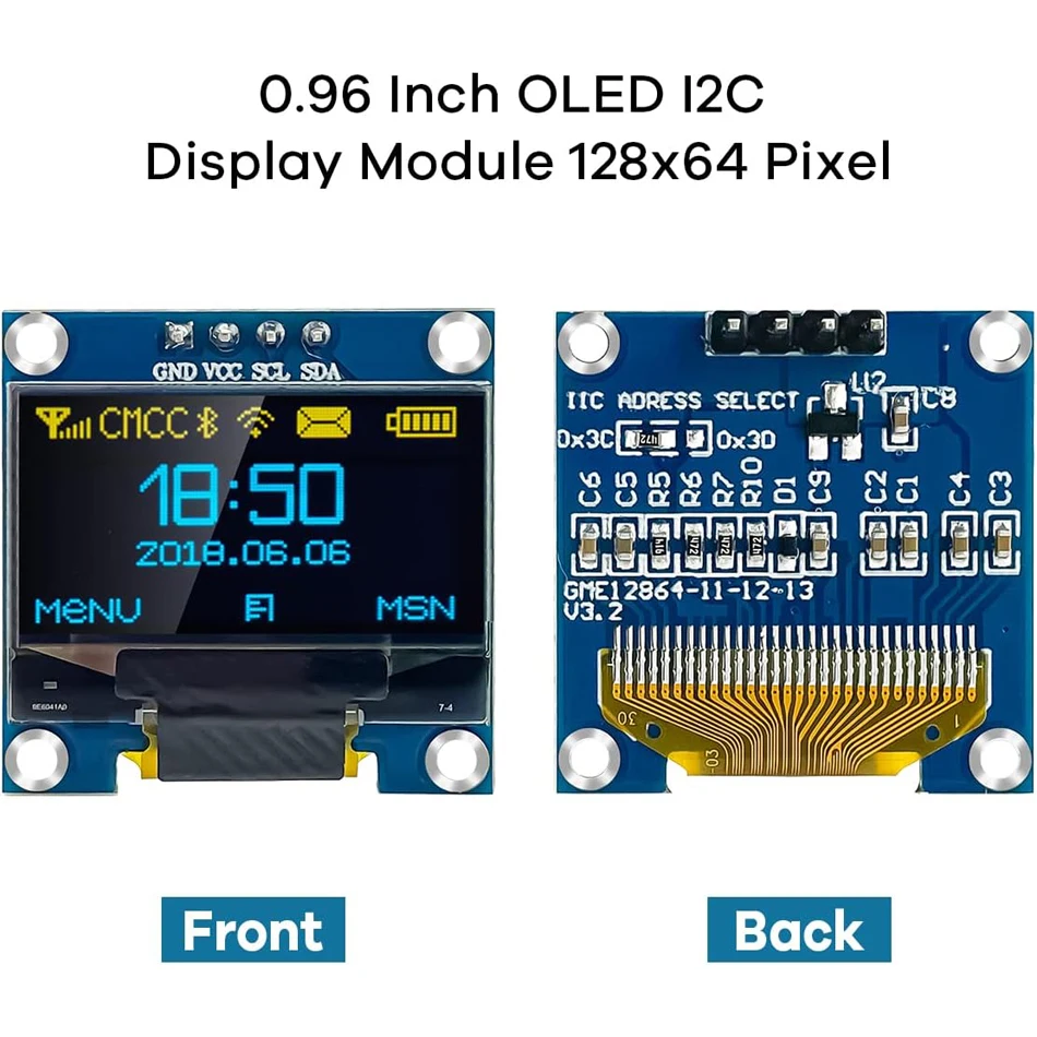
0.96 Inch OLED SSD1306 Display Module: the I2C display used in the examples, commonly at address 0x3C. BME280 Sensor Module: the I2C temperature, humidity and pressure sensor, commonly at 0x76 or 0x77. 2.0 Inch TFT LCD ST7789 Display: the SPI display for projects that need speed and colour.
Sources
- I2C vs SPI vs UART guide, wiring, speed and addressing
- I2C vs SPI vs UART, sensor and display picks
- I2C vs SPI vs UART protocols explained, with Arduino and ESP32 examples
- Espressif ESP32 Series Datasheet v5.3
Last updated: 2026-11-21. Search volume: not verified. Product links use the store short link form with the product ID; confirm the product slug at publish time.