
ESP32 WiFi Sensor Telemetry: Live Dashboard with BME280
This ESP32 WiFi sensor telemetry build uses an ESP32 DevKit V1 with a BME280 sensor to serve a live temperature, humidity and pressure dashboard on your local Wi-Fi network. The sensor connects over I2C on GPIO 21 and GPIO 22, the ESP32 runs a small web server, and any phone or laptop on the same network opens the page.
Quick facts
| Item | Value |
|---|---|
| Sensor | BME280, temperature, humidity, pressure |
| Interface | I2C, address 0x76 or 0x77 |
| Supply | 3.3 V from the ESP32; bare chip maximum is 3.6 V |
| Accuracy | Temperature plus or minus 0.5 C, humidity plus or minus 3 percent, pressure plus or minus 1 hPa |
| Update rate | Page refreshes every 5 seconds |
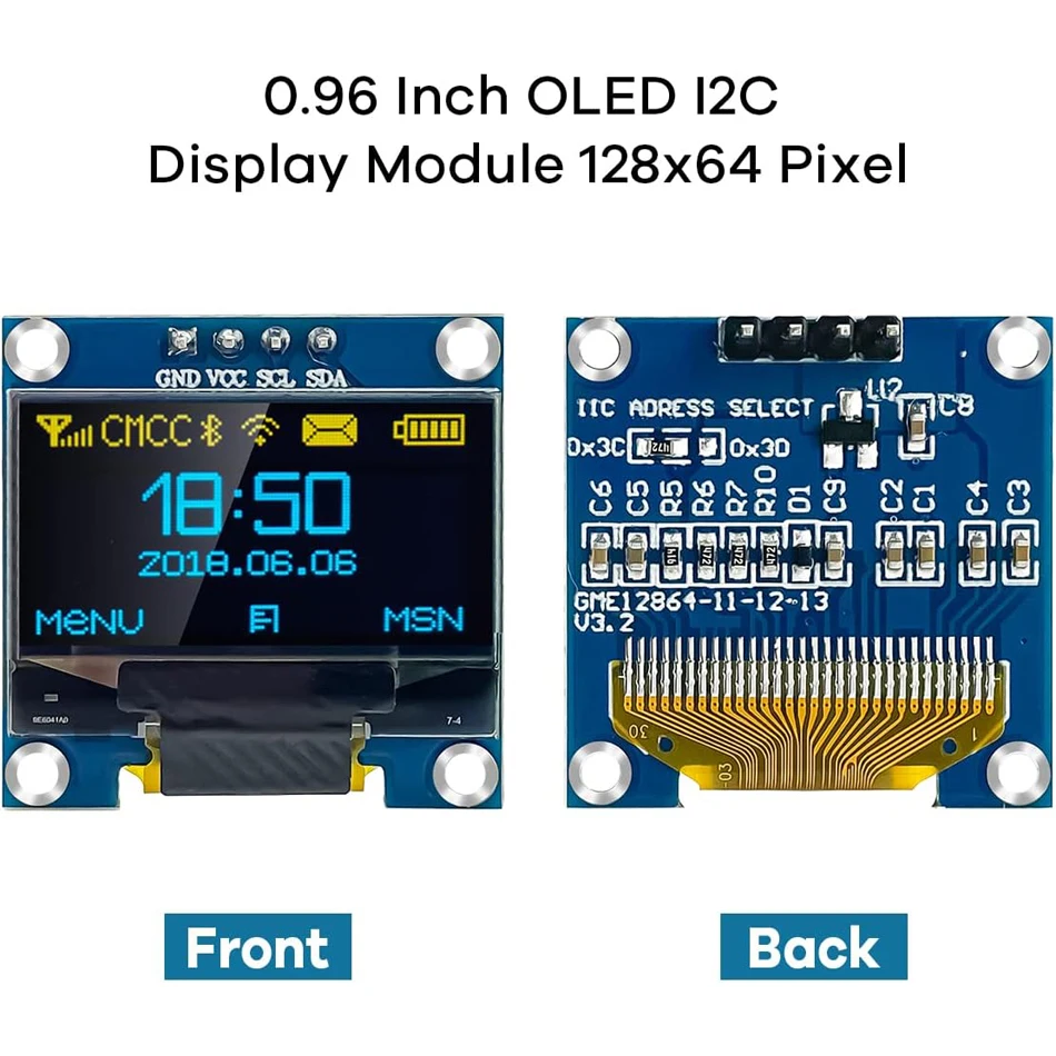
| Display | 0.96 inch SSD1306 OLED mirrors the readings locally |
ESP32 WiFi sensor telemetry: how does the dashboard work?
The BME280 measures temperature, relative humidity and barometric pressure in one chip. The ESP32 reads it over I2C, then serves the values as a web page and as a small JSON endpoint. Your browser fetches the JSON every 5 seconds and updates the numbers without reloading the page.
The dashboard runs on your local network only. The ESP32 joins your Wi-Fi as a station, prints its IP address to the serial monitor, and serves the page at that address. Anyone on the same network can open it. Nothing leaves your network, and no account is needed.
The OLED display mirrors the readings on the bench. It is optional, but it helps when the network is down. The OLED uses the same I2C bus as the BME280, with its own address, so no extra pins are needed.
What does the BME280 measure, and how accurate is it?
The BME280 measures temperature from -40 to +85 C, relative humidity from 0 to 100 percent, and pressure from 300 to 1100 hPa. Bosch rates temperature accuracy at plus or minus 0.5 C from 0 to 65 C, humidity at plus or minus 3 percent, and pressure at plus or minus 1 hPa. Those figures come from the Bosch BME280 datasheet, revision 1.24, February 2024 (BST-BME280-DS001-24).
Pressure also works as an altimeter, because pressure falls with altitude. The sensor relative accuracy is plus or minus 0.12 hPa from 700 to 900 hPa at 25 to 40 C, which is about 3 feet of altitude. Do not expect survey accuracy from a bench sensor, but it is ample for weather trends and room monitoring.
Keep the sensor away from heat sources. The ESP32 board warms the air around it, and a BME280 mounted tight against the board reads high. Mount it on short jumper wires away from the board and out of direct sun.
How do you wire the BME280 and the OLED?
Both parts use I2C. Connect the BME280 VCC to the ESP32 3V3 pin and its GND to ground. Connect SDA to GPIO 21 and SCL to GPIO 22, which are the default I2C pins on the ESP32 DevKit V1. Connect the OLED the same way, on the same two wires.
The bare BME280 chip runs on 1.71 to 3.6 V and is not 5 V tolerant, so power it from 3.3 V on an ESP32. The stocked module lists 5 V support, which means it carries a regulator, but 3.3 V is safe for every version of the board. The OLED module also runs on 3.3 V.
The BME280 I2C address is 0x76 or 0x77, set by the SDO pin. Most small breakout boards default to 0x76. The code below tries 0x76 first and falls back to 0x77, so either board works. If the sensor is not found, run an I2C scanner sketch and read the address it reports.
How do you read the sensor in code?
Install the Adafruit BME280 Library and the Adafruit Unified Sensor library from the Arduino Library Manager. The sketch creates an Adafruit_BME280 object, starts it with begin(0x76), and reads temperature, humidity and pressure with readTemperature(), readHumidity() and readPressure(). Pressure comes back in Pascals, so divide by 100 to get hPa.
The web server is the ESP32 WebServer library, which ships with the core. The root handler returns an HTML page. The /data handler returns JSON with the three readings. A small JavaScript timer in the page fetches /data every 5 seconds and writes the values into the page.
The OLED uses the Adafruit SSD1306 library. It draws the same three values on the 128 by 64 display. If you skip the OLED, delete the display code and the sketch still works.
Wiring
Wire the build with the power off. Check every connection in the table before you connect any battery or USB cable.
| From | To | Notes |
|---|---|---|
| BME280 VCC | ESP32 3V3 | 3.3 V; bare chip maximum is 3.6 V, never use 5 V on a bare chip |
| BME280 GND | ESP32 GND | Common ground |
| BME280 SDA | ESP32 GPIO 21 | Default I2C data pin |
| BME280 SCL | ESP32 GPIO 22 | Default I2C clock pin |
| BME280 SDO | GND | Sets I2C address 0x76; tie to 3V3 for 0x77 |
| BME280 CSB | 3V3 | Tie high for I2C mode |
| OLED VCC | ESP32 3V3 | 3.3 V logic |
| OLED GND | ESP32 GND | Common ground |
| OLED SDA | ESP32 GPIO 21 | Shared I2C bus with the BME280 |
| OLED SCL | ESP32 GPIO 22 | Shared I2C bus with the BME280 |
Power budget
The ESP32 draws about 80 to 160 mA with Wi-Fi on, and peaks near 240 mA while transmitting. The BME280 draws only a few microamps between readings, and the OLED draws about 20 mA with the display lit. A USB 5 V supply at 500 mA covers the whole build with margin.
Do not run this build from a small battery and expect days of life. Wi-Fi on, all the time, is the expensive part. If you need battery life, read the deep sleep sensor node build in Battery-Powered ESP32 Sensor Node: Deep Sleep and Power Budget, which wakes, reads, sends, and sleeps again.
Keep the USB cable short and the supply stable. A weak cable drops voltage when Wi-Fi transmits, and the ESP32 resets. That reset looks like a code fault, but it is a power fault. The troubleshooting post on brownout resets covers the symptoms.
Build steps
- Install the Adafruit BME280 Library, Adafruit Unified Sensor, and Adafruit SSD1306 libraries from the Library Manager.
- Wire the BME280 and the OLED to the ESP32 from the wiring table. Keep the sensor away from the board heat.
- Edit the Wi-Fi name and password in the sketch, then upload it to the ESP32 DevKit V1.
- Open the serial monitor at 115200 baud and copy the IP address the board prints after it connects.
- Open that IP address in a browser on the same network. The dashboard should show live temperature, humidity and pressure.
- Check the OLED. It should mirror the same three values. If the OLED is blank, check its I2C address with a scanner sketch.
- Leave the board running for an hour and watch the readings. Temperature should track the room, and pressure should drift slowly with the weather.
Code
Libraries: Adafruit BME280 Library, Adafruit Unified Sensor, Adafruit SSD1306, Adafruit GFX Library (all from the Arduino Library Manager). Board: ESP32 DevKit V1. The sketch tries BME280 address 0x76 first, then 0x77.
// ESP32 WiFi sensor telemetry with BME280 + SSD1306 OLED
// Board: ESP32 DevKit V1. Libraries: Adafruit BME280, Adafruit SSD1306.
#include
#include
#include
#include
#include
#include
#include
const char* WIFI_SSID = "YOUR_WIFI_NAME"; // Replace with your network
const char* WIFI_PASS = "YOUR_WIFI_PASSWORD"; // Replace with your password
Adafruit_BME280 bme; // I2C, address 0x76 or 0x77
Adafruit_SSD1306 display(128, 64, &Wire, -1);
WebServer server(80);
float temperatureC = 0, humidityPct = 0, pressureHpa = 0;
void readSensor() {
temperatureC = bme.readTemperature(); // Degrees C
humidityPct = bme.readHumidity(); // Percent relative humidity
pressureHpa = bme.readPressure() / 100.0F; // Pascals to hPa
}
void handleRoot() {
// Simple page; JavaScript fetches /data every 5 seconds.
String html = ""
"ESP32 Sensor Telemetry "
"ESP32 Sensor Telemetry
"
"Temperature: -- C
"
"Humidity: -- %
"
"Pressure: -- hPa
"
"";
server.send(200, "text/html", html);
}
void handleData() {
readSensor();
String json = "{\"t\":" + String(temperatureC, 1)
+ ",\"h\":" + String(humidityPct, 1)
+ ",\"p\":" + String(pressureHpa, 1) + "}";
server.send(200, "application/json", json);
}
void setup() {
Serial.begin(115200);
Wire.begin(21, 22); // SDA, SCL on ESP32 DevKit V1
if (!bme.begin(0x76)) {
if (!bme.begin(0x77)) {
Serial.println("BME280 not found. Check wiring and address.");
while (1) delay(100);
}
}
if (!display.begin(SSD1306_SWITCHCAPVCC, 0x3C)) {
Serial.println("OLED not found. Check wiring and address.");
}
WiFi.begin(WIFI_SSID, WIFI_PASS);
while (WiFi.status() != WL_CONNECTED) delay(500);
Serial.print("Dashboard at http://");
Serial.println(WiFi.localIP());
server.on("/", handleRoot);
server.on("/data", handleData);
server.begin();
}
void loop() {
server.handleClient();
static unsigned long lastDisplay = 0;
if (millis() - lastDisplay > 5000) {
lastDisplay = millis();
readSensor();
display.clearDisplay();
display.setTextSize(1);
display.setTextColor(SSD1306_WHITE);
display.setCursor(0, 0);
display.print("Temp: "); display.print(temperatureC, 1); display.println(" C");
display.print("Hum: "); display.print(humidityPct, 1); display.println(" %");
display.print("Pres: "); display.print(pressureHpa, 1); display.println(" hPa");
display.display();
}
}
Test and tune it
Open the dashboard on two devices at once. Both should update every 5 seconds. If one stalls, the Wi-Fi signal at the board is weak. Move the board closer to the router or raise the antenna area clear of metal.
Compare the temperature against a room thermometer. A reading 2 to 3 C high usually means the sensor sits too close to the ESP32 board. Move it onto longer jumper wires and retest.
If the page loads but the numbers stay at dashes, open the /data address directly in the browser. It should return JSON such as {“t”:21.5,”h”:44.0,”p”:1013.2}. If it returns an error, the BME280 read failed, so check the I2C address with a scanner sketch.
FAQ
Why does the BME280 show 0x76 on one board and 0x77 on another?
The SDO pin sets the address. Tied to ground it is 0x76, tied to the supply it is 0x77. Different breakout boards ship with different defaults. The code tries 0x76 first, then 0x77.
Can I view the dashboard from outside my home?
Not as built. The ESP32 serves the page on your local network only. Remote access needs port forwarding or a cloud service, which adds security risk. Keep it local unless you know how to secure it.
How often should the sensor read?
Every 5 seconds is ample for room weather. The BME280 itself draws almost nothing, but the Wi-Fi radio dominates power. Faster reads do not improve accuracy.
Why is the temperature higher than the room thermometer?
The ESP32 board warms the air around it. Mount the BME280 away from the board on short wires, out of direct sun, and the reading will track the room.
What is the difference between this build and a weather station?
A weather station shows readings on a local display. This build adds Wi-Fi, so any device on the network sees live data. The local weather station post on this site covers the display-only version.
Parts used
Build it with the ESP32 DevKit V1 Development Board, 30-Pin WROOM-32, the BME280 Temperature, Humidity and Barometric Pressure Sensor Module, 5V, I2C and SPI, and the 0.96 Inch OLED Display Module, SSD1306, I2C, 128×64, for Arduino / ESP32 / ESP8266. For the protocol behind the wiring, see I2C vs SPI vs UART: Which Protocol for Your Sensor or Display, and for the battery version of this node see Battery-Powered ESP32 Sensor Node: Deep Sleep and Power Budget.
Sources
- Bosch BME280 datasheet, revision 1.24, February 2024 (BST-BME280-DS001-24)
- Adafruit BME280 breakout guide
- Espressif Arduino-ESP32 documentation
- Espressif ESP32 Series Datasheet
Last updated: 2026-11-21. Search volume: not verified. Product links use the store short link form with the product ID; confirm the product slug at publish time.