
Arduino IDE ESP32 Setup: Install and Upload in 9 Steps
Arduino IDE ESP32 setup starts with Arduino IDE 2: add the Espressif board manager URL to Preferences, install the esp32 package by Espressif Systems in Boards Manager, then select your board and serial port. The stable URL is https://espressif.github.io/arduino-esp32/package_esp32_index.json. Upload the Blink example to confirm the install works.
Quick facts
- Arduino IDE 2 is the current IDE. Version 1.8 also works, but IDE 2 is the path in this guide.
- Board package: esp32 by Espressif Systems, installed through Boards Manager.
- Board manager URL: https://espressif.github.io/arduino-esp32/package_esp32_index.json
- First sketch: File, Examples, 01.Basics, Blink. Built-in LED is GPIO 2 on a classic DevKit V1 board.
- Logic level is 3.3 V. Never feed 5 V into a GPIO pin.
What do you need before you start?
Gather one ESP32 board, one USB data cable, and a computer with an internet connection. A charge-only cable will power the board but it cannot upload code, so test the cable with a phone file transfer first if you are unsure. The board in this guide is the 30-pin DevKit V1, but the same steps work for the S3 DevKitC-1 and the C3 SuperMini. Keep the board on a clear bench and do not connect motors, servos, or sensors yet. A bare board removes every wiring variable from the first upload.
Download Arduino IDE 2 from the official Arduino software page. Install it with the default options and let it install any USB driver it offers. On Windows, the installer may ask for permission to install a driver. Accept it. On Linux, add your user to the dialout group so the IDE can open the serial port. The command is sudo usermod -a -G dialout $USER, followed by a logout and login. On macOS, no extra driver step is needed for most boards.
How do you add the ESP32 board package?
Open Arduino IDE and go to File, Preferences on Windows and Linux, or Arduino IDE, Settings on macOS. Find the field named Additional boards manager URLs. Paste this URL on its own line: https://espressif.github.io/arduino-esp32/package_esp32_index.json. If the field already holds other URLs, add this one on a new line. Click OK to save. This URL points to a JSON index that tells Boards Manager where to fetch the Espressif package. Do not paste a GitHub repository page instead. The repository page is source code, and Boards Manager cannot read it.
Open Boards Manager from the left sidebar icon or from Tools, Board, Boards Manager. Type esp32 in the search box. Find esp32 by Espressif Systems and click Install. The download is large because it includes the compiler toolchain, so allow several minutes on a slow connection. When the install finishes, close Boards Manager. Open Tools, Board and confirm that an ESP32 Arduino section now lists dozens of boards. If the section is missing, restart the IDE and check the URL again for a typo.
Which board entry matches your board?
Pick the entry that matches the chip on your board, not the name on the shop listing. A 30-pin DevKit V1 with a WROOM-32 module uses ESP32 Dev Module. An S3 DevKitC-1 uses ESP32S3 Dev Module. A C3 SuperMini uses ESP32C3 Dev Module. The wrong entry can still compile, but the pin map, flash size, and upload settings may be wrong. Check the module marking on the metal shield if you are unsure. The shield prints ESP32-WROOM-32, ESP32-S3-WROOM-1, or ESP32-C3-WROOM-02. Match that marking to the board entry.
Set the remaining Tools menu options to their defaults for the first upload. Upload Speed at 921600 works on most boards with a good cable. If uploads fail, lower it to 115200. Flash Size should match the module on your board. Most DevKit boards carry 4 MB of flash. Leave Partition Scheme on Default 4MB with spiffs for now. The partition guide in this series explains when to change it. Do not change Flash Mode or Flash Frequency unless the board documentation tells you to.
How do you connect the board and pick the port?
Connect the board with the USB data cable. Watch for a power LED on the board. Open Tools, Port and look for a new entry. On Windows it appears as COM3, COM4, or a higher number. On macOS it appears as a cu.usbserial or cu.SLAB_USBtoUART device. On Linux it appears as /dev/ttyUSB0 or /dev/ttyACM0. Unplug the board and watch the entry disappear, then plug it back in. That test proves the port belongs to your board. If no port appears, the cable or the USB driver is the problem, and the driver fix guide in this series covers CH340 and CP2102 chips.
Select the port that appeared. Keep the board connected and do not open the Serial Monitor yet. The Serial Monitor holds the port open, and an upload cannot use a port that is already open. Close any other program that talks to serial ports, including a second IDE window and a terminal monitor. One program owns the port at a time. If the port list is empty, try a different USB port on the computer and a different cable before you change any IDE setting.
What does the first sketch do?
The Blink example turns the on-board LED on and off once per second. It tests the whole chain at once: compile, upload, and run. It uses no libraries and no wiring, so a failure points at the install or the connection, not at your circuit. Open File, Examples, 01.Basics, Blink. The sketch sets the built-in LED pin as an output in setup and toggles it in loop. On a classic DevKit V1, LED_BUILTIN is GPIO 2. On S3 and C3 boards, the built-in LED pin differs, so use the board definition LED_BUILTIN and do not hard-code a pin number from another board.
Click Upload, which is the right arrow in the toolbar. The IDE compiles the sketch, then prints Connecting in the output panel. A successful upload ends with Hard resetting via RTS pin and Done uploading. The LED starts to blink. If the output stops at Connecting with rows of dots, the board did not enter download mode. Hold the BOOT button, click Upload again, and release BOOT when Connecting appears. That sequence is covered in full in the upload failure guide in this series.
What if the upload fails or the board is not found?
Work the chain in order: cable, port, driver, board selection, then BOOT button. Swap the cable first, because a charge-only cable is the most common cause. Next, confirm the port in Tools, Port. Then check Device Manager on Windows or the port list on macOS and Linux for the USB chip. A CH340 board shows as USB-SERIAL CH340. A CP2102 board shows as Silicon Labs CP210x USB to UART Bridge. Install the matching driver from the chip maker and restart the IDE. Re-check the board entry after that, because the wrong entry can also fail an upload.
Do not change three settings at once. Change one thing, retry the upload, and note the result. Keep the output panel visible. The exact error line matters. A fatal error occurred: Failed to connect to ESP32: Timed out waiting for packet header means the chip never entered download mode. A port busy error means another program holds the port. A sketch too big error means the partition scheme is too small. Each error has its own fix guide in this series, and each fix starts from the exact message.
Step-by-step: Arduino IDE ESP32 setup and upload Blink
- Install Arduino IDE 2 from the official Arduino software page and launch it.
- Open File, Preferences and add https://espressif.github.io/arduino-esp32/package_esp32_index.json to Additional boards manager URLs, then click OK.
- Open Tools, Board, Boards Manager, search for esp32, and install esp32 by Espressif Systems.
- Open Tools, Board and select the entry that matches your chip, such as ESP32 Dev Module for a DevKit V1 board.
- Connect the board with a USB data cable and select the new port under Tools, Port.
- Open File, Examples, 01.Basics, Blink.
- Click Upload and wait for Done uploading in the output panel.
- Watch the on-board LED blink once per second.
- Open Tools, Serial Monitor at 115200 baud only after the upload finishes, if you want to see serial output from a later sketch.
Board entry to pick for each board in this guide
| Board in stock | Chip | Board entry in Arduino IDE | USB chip |
|---|---|---|---|
| ESP32 DevKit V1, 30-pin | ESP32 WROOM-32 | ESP32 Dev Module | CP2102 or CH340, varies by batch |
| ESP32-S3 DevKitC-1 | ESP32-S3 | ESP32S3 Dev Module | Native USB, plus a CP2102N or CH343P bridge on the UART port (varies by revision) |
| ESP32-C3 SuperMini | ESP32-C3 | ESP32C3 Dev Module | Native USB |
First code to run
Paste this sketch into a new sketch if the built-in Blink example is not listed. It is the same code as File, Examples, 01.Basics, Blink, with comments added.
// Blink for ESP32 in Arduino IDE
// Board: ESP32 Dev Module (DevKit V1) or the entry that matches your chip
// Library: none. Uses only the Arduino core by Espressif Systems.
// LED_BUILTIN is GPIO 2 on a classic DevKit V1. Other boards differ.
void setup() {
  pinMode(LED_BUILTIN, OUTPUT);  // Set the on-board LED pin as an output
}

void loop() {
  digitalWrite(LED_BUILTIN, HIGH);  // Turn the LED on
  delay(1000);                      // Wait 1000 ms (1 second)
  digitalWrite(LED_BUILTIN, LOW);   // Turn the LED off
  delay(1000);                      // Wait 1000 ms (1 second)
}
If LED_BUILTIN is not defined for your board entry, replace it with the GPIO number of the on-board LED from the board documentation. Do not guess the pin number.
Frequently asked questions
Do I need the board manager URL in Arduino IDE 2?
Yes. Arduino IDE 2 does not list the esp32 package by Espressif Systems until you add the URL from this guide to Additional boards manager URLs. Without it, a search for esp32 returns no results, or only the official Arduino Nano ESP32 board. Add the URL first, then install the package.
Which ESP32 board should a beginner buy first?
A classic 30-pin DevKit V1 is the safest first board. It has the widest tutorial coverage, a 30-pin layout, and both WiFi and Bluetooth. Move to an S3 board when you need USB, more GPIO pins, or camera support.
Why does my ESP32 need a BOOT button press to upload?
The upload tool must restart the chip with GPIO 0 held low so the ROM bootloader listens. Most boards do this automatically through the USB chip. When the automatic circuit is missing or slow, hold BOOT during the Connecting message and release it when the upload starts.
Can I use Arduino IDE 1.8 instead of IDE 2?
Yes. The same board manager URL and the same esp32 package work in IDE 1.8. IDE 2 is the current version, and its Boards Manager and Serial Monitor are easier to use. Use IDE 2 for a new install.
Is the ESP32 5 V tolerant?
No. ESP32 GPIO pins run at 3.3 V logic. Never apply 5 V to a GPIO pin. Power the board through USB or the 5 V pin, and use a level shifter when you connect a 5 V sensor or logic output.
Parts used in this guide
This guide uses the ESP32 DevKit V1 board for the first upload. The same install steps work for the S3 DevKitC-1 board and the C3 SuperMini board linked below.
- ESP32 DevKit V1 Development Board, 30-Pin WROOM-32, WiFi + Bluetooth, Dual-Core
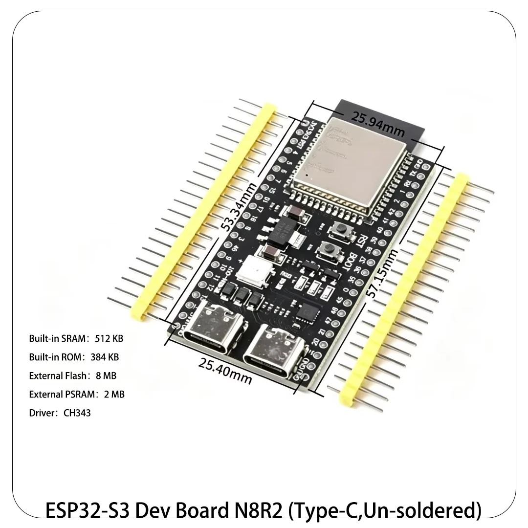
- ESP32-S3 Development Board DevKitC-1 N8R2 N16R8
- ESP32-C3 SuperMini Development Board 4-Pack
Related guides
- ESP32 vs ESP32-S3 vs ESP32-C3 vs ESP32-C6: Which Chip for Your Project
- How to Set Up PlatformIO for ESP32 in VS Code
- ESP-IDF First Project: Build and Flash an ESP32
Sources
- Espressif: Getting Started with ESP32 Arduino
- Espressif Arduino-ESP32 installing guide
- ESP32 install guide
Last updated: 2026-11-21