
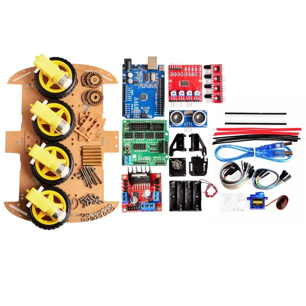
L298N Robot Car: Wire and Drive Two DC Motors
Wire an L298N between your battery and two TT motors, then drive them from an ESP32 with PWM on the enable pins. The L298N handles up to 2 A per channel, drops about 2 V across the bridge, and needs its own motor supply. The ESP32 only sends low-current direction and speed signals, and the supplies share only a ground.
Quick facts
| Item | Value |
|---|---|
| Driver | L298N dual H-bridge, 2 A per channel, 3 A peak non-repetitive for 100 ms |
| Motor supply | 5 to 35 V on the module, up to 46 V on the bare chip |
| Logic supply | 4.5 to 7 V; onboard 5 V regulator with jumper |
| Voltage drop | 1.8 to 3.2 V at 1 A, up to 4.9 V at 2 A |
| Motors | 2 x TT 130 gear motors, 3 to 6 V |
| Speed control | PWM on ENA and ENB, 0 to 255 |
L298N robot car: what does the L298N do?
The L298N is a dual H-bridge driver built on the ST L298 chip. It lets a microcontroller run two DC motors in either direction, at variable speed, from a supply the microcontroller could never deliver itself. Each channel switches up to 2 A of continuous current, with a 3 A peak allowed only non-repetitively for 100 ms.
An H-bridge is four switches arranged so the motor current can flow either way. The IN1 and IN2 pins set the direction for the first motor, and IN3 and IN4 set it for the second. The ENA and ENB pins enable each channel, and a PWM signal on an enable pin sets the speed. With the enable jumpers fitted, each motor runs at full speed whenever the direction pins command movement.
The bridge is built from bipolar transistors, not MOSFETs, so it drops voltage. At 1 A the drop is 1.8 to 3.2 V, and at 2 A it reaches 4.9 V. That drop becomes heat in the chip, which is why the module carries a large heatsink. A 12 V supply gives the motor about 10 V. A 6 V supply gives the motor about 4 V.
When do you remove the 5 V jumper?
The module has an onboard 5 V regulator and a jumper that enables it. With the jumper fitted and a motor supply of 12 V or less, the regulator makes 5 V on the 5 V pin, and you can use that pin to power your logic. With a motor supply above 12 V, remove the jumper first, or the regulator overheats.
With the jumper removed, the 5 V pin becomes an input. You must feed 5 V into it yourself to power the chip logic. This build uses a 6 V motor pack, so the jumper stays on. The regulator then supplies the logic, and the ESP32 runs from its own USB supply.
Never connect two 5 V supplies to the same pin. If the jumper is fitted, leave the 5 V pin unconnected, or the regulator and your other supply will fight. If the jumper is removed, feed 5 V in and do not expect 5 V out.
How do you wire the L298N to an ESP32?
Connect the motor battery positive to the 12 V terminal and the battery negative to GND. Connect the two TT motors to OUT1 and OUT2 for the left motor, and OUT3 and OUT4 for the right motor. Connect ENA, IN1, IN2, ENB, IN3 and IN4 to the ESP32 pins in the wiring table.
The L298N inputs read high from 2.3 V, so the ESP32 3.3 V logic drives them directly. No level shifter is needed. Join the battery negative to the ESP32 ground. Without that common ground, the direction signals have no reference and the motors will not respond.
Remove the ENA and ENB jumpers before you connect PWM. With the jumpers fitted, the enable pins sit at 5 V and the motors run at full speed regardless of your code. With the jumpers removed, the ESP32 PWM signal on each enable pin sets the speed from 0 to 255.
How does PWM speed control work?
PWM switches the enable pin on and off about 1,000 times per second at the core 3.3.13 default of 1 kHz. The motor sees the average voltage, so a 50 percent duty cycle gives about half speed. The sketch below uses analogWrite() with values from 0 to 255. A value of 0 stops the motor, and 255 runs it at full speed for the supply voltage.
TT motors stall at low PWM values. Below about 80 out of 255, many TT motors do not turn at all, because the average voltage cannot overcome friction. Start your speed tests at 150 and work down. If the car creeps at low speed, that is normal for a geared TT motor on an L298N with a 2 V drop.
Direction and speed are separate. The IN pins set forward or reverse, and the enable PWM sets how fast. To stop, set the enable PWM to zero. To brake hard, set both IN pins the same way, but a simple stop is enough for a first build.
Wiring
Wire the build with the power off. Check every connection in the table before you connect any battery or USB cable.
| From | To | Notes |
|---|---|---|
| Battery box positive | L298N 12 V terminal | Motor supply, 6 V from 4 AA cells |
| Battery box negative | L298N GND and ESP32 GND | Common ground is required |
| L298N OUT1, OUT2 | Left TT motor | Swap these two wires to fix a reversed wheel |
| L298N OUT3, OUT4 | Right TT motor | Swap these two wires to fix a reversed wheel |
| ESP32 GPIO 25 | L298N ENA | Remove the ENA jumper; PWM speed, left motor |
| ESP32 GPIO 27 | L298N IN1 | Left motor direction A |
| ESP32 GPIO 14 | L298N IN2 | Left motor direction B |
| ESP32 GPIO 26 | L298N ENB | Remove the ENB jumper; PWM speed, right motor |
| ESP32 GPIO 33 | L298N IN3 | Right motor direction A; GPIO 33 is used instead of GPIO 12, which is a flash-voltage strapping pin and must stay low at boot |
| ESP32 GPIO 13 | L298N IN4 | Right motor direction B |
| L298N 5 V pin | Leave unconnected | Jumper fitted at 6 V, so the regulator makes 5 V here; do not feed 5 V in as well |
| USB 5 V | ESP32 USB port | Logic supply only; motor current never passes through USB |
Power budget
The motors run from 4 AA cells at about 6 V into the L298N. The bridge drops about 2 V, so each TT motor sees about 4 V. Two TT motors at full load draw about 1 to 2 A together, which the L298N handles with its heatsink. At 1 A per channel the chip dissipates about 2 W as heat, so give it airflow and do not cover the heatsink.
The ESP32 runs from USB 5 V and draws about 80 to 160 mA with the radio on. The L298N logic draws about 40 to 60 mA from the motor supply through its onboard regulator. The two supplies share only a ground wire. Never power the motors from the ESP32 5 V pin, and never power the ESP32 from the L298N 5 V pin while USB is also connected, because two 5 V sources will fight.
If you raise the motor supply above 12 V, remove the 5 V jumper first and feed 5 V into the 5 V pin yourself. Above 12 V the onboard regulator overheats. The TT motors in this build are rated 3 to 6 V, so a 6 V pack is the right match and the jumper stays on.
Build steps
- Assemble the chassis kit, fit the TT motors and wheels, and mount the L298N and the ESP32 on the top plate.
- Connect the motors to OUT1 and OUT2, and OUT3 and OUT4. Connect the battery box to the 12 V terminal and GND. Leave the 5 V jumper on for a 6 V pack.
- Remove the ENA and ENB jumpers. Wire the six control pins from the wiring table and join the battery negative to the ESP32 ground.
- Upload the sketch below to the ESP32 DevKit V1. Keep the car lifted off the floor for the first test.
- Open the serial monitor at 115200 baud and type f, b, l, r, or s, then press Enter. Each key drives the car forward, back, left, right, or stop.
- Set the car on the floor and drive it forward. If a wheel runs backward, swap that motor’s two wires at the L298N output.
- Test low speed. If the motors stall below a PWM value of about 80, raise your minimum drive speed in the sketch.
Code
Libraries: none beyond the ESP32 Arduino core. Board: ESP32 DevKit V1, Arduino core 3.3.13 (analogWrite arrived in core 3.0). Control the car from the serial monitor: type f, b, l, r, or s and press Enter.
// L298N robot car: two TT motors, PWM speed, serial control
// Board: ESP32 DevKit V1, Arduino core 3.3.13. No extra libraries needed.
const int ENA = 25;  // Left motor PWM (remove the ENA jumper)
const int IN1 = 27;  // Left motor direction A
const int IN2 = 14;  // Left motor direction B
const int ENB = 26;  // Right motor PWM (remove the ENB jumper)
const int IN3 = 33;  // Right motor direction A (GPIO 12 avoided: strapping pin)
const int IN4 = 13;  // Right motor direction B
const int SPEED = 200;  // 0 to 255; TT motors stall below about 80

void driveMotor(int pwmPin, int inA, int inB, int speed) {
  if (speed >= 0) {
    digitalWrite(inA, HIGH);
    digitalWrite(inB, LOW);
    analogWrite(pwmPin, speed);
  } else {
    digitalWrite(inA, LOW);
    digitalWrite(inB, HIGH);
    analogWrite(pwmPin, -speed);
  }
}

void drive(int left, int right) {
  driveMotor(ENA, IN1, IN2, left);
  driveMotor(ENB, IN3, IN4, right);
}

void stopCar() {
  analogWrite(ENA, 0);
  analogWrite(ENB, 0);
}

void setup() {
  Serial.begin(115200);
  pinMode(ENA, OUTPUT); pinMode(IN1, OUTPUT); pinMode(IN2, OUTPUT);
  pinMode(ENB, OUTPUT); pinMode(IN3, OUTPUT); pinMode(IN4, OUTPUT);
  stopCar();
  Serial.println("Type f, b, l, r, or s, then Enter.");
}

void loop() {
  if (Serial.available() > 0) {
    char c = Serial.read();
    if (c == 'f') drive(SPEED, SPEED);        // Forward
    else if (c == 'b') drive(-SPEED, -SPEED); // Reverse
    else if (c == 'l') drive(-SPEED, SPEED);  // Turn left
    else if (c == 'r') drive(SPEED, -SPEED);  // Turn right
    else if (c == 's') stopCar();             // Stop
  }
}
Test and tune it
Lift the car and type f. Both wheels should spin forward at the same speed. If one wheel is slower, check that its motor wires are tight in the screw terminal and that its enable PWM pin is connected.
Type s and confirm both wheels stop within a second. A wheel that keeps spinning has a stuck enable jumper or a shorted IN pin. Remove power and recheck the wiring table.
Drive the car on a hard floor, then on carpet. The car will slow on carpet because the TT motors draw more current under load and the L298N drop grows. That is normal. A MOSFET driver such as the TB6612FNG loses less voltage and is the next step if battery life matters.
FAQ
Why does my L298N get hot?
The bipolar bridge drops about 2 V, and that drop becomes heat. At 1 A per channel the chip dissipates about 2 W. The heatsink is supposed to get warm. Give it airflow and keep the current under 2 A per channel.
Do I remove the 5V jumper on the L298N?
Remove it when the motor supply is above 12 V, because the onboard regulator overheats. Leave it on at 12 V or less. With the jumper removed, feed 5 V into the 5 V pin yourself.
Why do the motors run slow on a 6 V battery?
The L298N drops about 2 V, so a 6 V pack gives each motor about 4 V. That is normal for this driver. A higher supply is not an option here: the pack is already 6 V and the TT motors are rated 3 to 6 V. A MOSFET driver such as the TB6612FNG loses less voltage and gives more speed.
Can the ESP32 drive the L298N directly?
Yes. The L298N inputs read high from 2.3 V, so 3.3 V logic works with no level shifter. Join the battery negative to the ESP32 ground so the signals share a reference.
Why does one wheel spin backward?
That motor is wired in reverse. Swap its two wires at the L298N output terminals. Do not fix it in code, because the wiring is the fault.
Parts used
Build it with the L298N Dual H-Bridge Motor Driver Module for Arduino, the Smart Robot Car Chassis Kit with Speed Encoder and Battery Box for Arduino, 2WD / 4WD, and the TT Motor 130 Gear Motor + 65mm Wheel, 3-6V DC, for Arduino Smart Car Robot, plus the ESP32 DevKit V1 Development Board, 30-Pin WROOM-32 as the controller. The wireless version is ESP-NOW Joystick Robot Car: Two ESP32 Boards, No Router, and the driver comparison is L298N vs TB6612 vs DRV8833: Which Motor Driver for Your Robot. For the driver behind the speed control, see How to Choose the Right Motor Drivers for Arduino Use.
Sources
Last updated: 2026-11-21. Search volume: not verified. Product links use the store short link form with the product ID; confirm the product slug at publish time.