Posted on

Build a Plant Monitor with DHT22 and MQ-2 Air Sensing

Plants do not complain until they are already dying. A small monitor that watches temperature, humidity, and air quality gives you the warning while there is still time to act. This build lives in a greenhouse, a grow tent, or on a sunny windowsill.

Parts list

NodeMCU ESP8266 development board with built-in OLED — controller, WiFi, and display in one. DHT22 / AM2302 temperature and humidity sensor module — the plant’s climate. MQ-2 smoke and combustible gas sensor module — air quality and fumes. A Raspberry Pi 4 power supply, 5V 3A USB-C works fine as a bench supply for the NodeMCU too — check the plug and voltage on the product page before you order.

What the sensors do

The DHT22 measures 0 to 100% relative humidity (plus or minus 2%) and -40 to 80 degrees C (plus or minus 0.5 degrees C) over a single data pin, on 3.3 to 5.5V. That covers the temperature and humidity range of any indoor grow space. The MQ-2 detects smoke, liquefied gas, butane, propane, methane, alcohol, and hydrogen over a range of 300 to 10,000 ppm. It gives both analog and digital outputs with an adjustable threshold potentiometer, so you can set a trip point for a warning. Its heater runs at 5.0V, it responds in 10 seconds or less and recovers in 30 seconds or less.

Code approach

Read the DHT22 every few seconds and the MQ-2 analog output on the same schedule. Show the numbers on the built-in OLED: temperature, humidity, and a simple air-quality reading. Set two thresholds — one for humidity too low (time to water or mist) and one for the MQ-2 digital output tripping (ventilate). On the NodeMCU you can also push the readings to a web page over WiFi so you can check the greenhouse from the house.

Tips

The MQ-2 heater needs warm-up time after power-on — give it a few minutes before you trust the readings. Keep the DHT22 away from direct sun and from the MQ-2’s own heater, or the temperature reads high. Mount the whole thing where air actually moves, not in a dead corner behind a pot. For a full weather readout, add the BMP280 pressure sensor from the weather station guide.

All parts in this guide ship from NY, USA. See the full list of guides on the Drone Guides page.

Related guides: Build a Weather Station with DHT22, BMP280, and OLED · NodeMCU ESP8266 with Built-In OLED: WiFi Projects with a Display
Posted on

Build a Weather Station with DHT22, BMP280, and OLED

A weather station is the project that uses everything: two sensors, a display, and a microcontroller that ties them together. Build it once on a breadboard, then put it in a box by the window and leave it running.

Parts list

NodeMCU ESP8266 development board with built-in OLED — controller and display in one, plus WiFi. DHT22 / AM2302 temperature and humidity sensor module — temperature and humidity. BMP280 barometric pressure and temperature sensor module — pressure and a second temperature reading. Or use the UNO R3 board with the separate 0.96 inch OLED display if you prefer the Arduino route.

What the sensors measure

The DHT22 measures relative humidity from 0 to 100% RH (plus or minus 2% accuracy) and temperature from -40 to 80 degrees C (plus or minus 0.5 degrees C), with a single-bus digital output that talks to any microcontroller over one data pin. It works on 3.3 to 5.5V and is factory calibrated. The module measures 28 x 12 x 10mm with a 4-pin interface: positive, ground, and Out (data to the microcontroller IO pin).

The BMP280 measures pressure from 300 to 1100 hPa with plus or minus 1 hPa absolute accuracy — good enough to use as an altimeter with about 1 meter accuracy — and temperature from -40 to +85 degrees C with plus or minus 1.0 degree accuracy. It talks over I2C (up to 3.4 MHz) or SPI (up to 10 MHz), runs on 1.8 to 5V, and draws just 2.7 microamps at a 1 Hz sampling rate. Note: the BMP280 is a pressure and temperature sensor only — it does not measure humidity. That is the BME280, a different sensor, sold separately.

Wiring and code approach

The DHT22 needs one data pin. The BMP280 shares the I2C bus with the OLED — same two wires, different addresses. Read both sensors once every few seconds, not continuously: the DHT22 is slow by design and the BMP280 barely sips power at 1 Hz, so there is nothing to gain by hammering them. Show temperature, humidity, and pressure on the OLED, and add a trend arrow for pressure — rising pressure usually means improving weather. On the NodeMCU, the same readings can go to a simple web page over WiFi.

Tips

Keep the sensors out of direct sun and away from the board’s own heat, or the temperature reads high. A small vented enclosure works. If the pressure reading looks wrong, check that you are reading hPa and not Pa. Add the TM1637 4-digit display as a second readout if you want the temperature visible across the room.

All parts in this guide ship from NY, USA. See the full list of guides on the Drone Guides page.

Related guides: NodeMCU ESP8266 with Built-In OLED: WiFi Projects with a Display · Which Display Should You Buy? OLED, TFT, and 7-Segment

Posted on

Rebuild a 3D Printer Axis: Bearings, Bushings, and Shaft Supports

A 3D printer axis that rattles, binds, or has play in it will never print straight, no matter how well you tune the slicer. The fix is mechanical: new bushings, solid shaft supports, and fresh bearings where they belong. This guide covers the rebuild.

Parts list

LM8UU / LM6UU linear ball bushings — the sliding part of the axis. SK8 / SK10 / SK12 / SK16 linear shaft supports — hold the shaft ends rigid. 608ZZ / 608RS ball bearings — idlers and pulleys. F623ZZ / F624ZZ / F625ZZ flanged ball bearings — housings where the flange does the retaining. M3 brass heat-set threaded inserts and the M3 stainless steel screw kit for printed brackets and mounts.

How the parts fit together

The linear bushings glide along the round shafts — LM8UU for 8mm shafts (8mm bore, 15mm outside diameter, 24mm long) or LM6UU for 6mm shafts (6mm bore, 12mm outside diameter, 19mm long). The recirculating ball design lets the bushing glide with minimal play. The shaft supports hold the ends of the shaft: each support bolts to the frame, with a clamping slot that grips the shaft firmly while still letting it be removed for maintenance. Four supports per pack, one at each end of the shaft. They pair with LM8UU, LM10UU, LM12UU, and LM16UU bushings on 8mm, 10mm, 12mm, and 16mm shafts.

The 608 bearings are 8mm bore x 22mm outside diameter x 7mm wide, pre-lubricated — 608ZZ with metal double shields, or 608RS with rubber seals for dust-proof running. The flanged bearings — F623zz 3x10x4mm, F624zz 4x13x5mm, F625zz 5x16x5mm, or F626zz 6x19x6mm — hold themselves in place in the housing by the flange, so no separate retaining clip is needed.

Rebuild method

Strip the axis down to the bare shafts. Clean the shafts and check them for wear — a grooved shaft eats new bushings fast, so replace it if you can feel a ridge. Fit the new bushings and slide them by hand: smooth, no catching, no play. Bolt the shaft supports down with the shaft in place so the alignment is set by the shaft itself, not by eye. Spin every idler bearing by hand; a gritty one gets replaced. Reassemble, then run the axis end to end by hand before you power it up.

Tips

Do not over-tighten the shaft supports — you will bow the shaft. If you print new brackets, the M3 heat-set inserts (M3 x 5.7 x 4.6mm, knurled brass) give you a real thread in PLA, ABS, or PETG. Keep a few spare 608s on hand; they are the bearing that wears out everywhere.

All parts in this guide ship from NY, USA. See the full list of guides on the Drone Guides page.

Related guides: Quiet Your 3D Printer: TMC2208 / TMC2209 Driver Upgrade · 3D Printer Bench Essentials: Springs, Gears, Tools, and Fasteners

Posted on

How to Upgrade a 3D Printer with TMC2208 or TMC2209

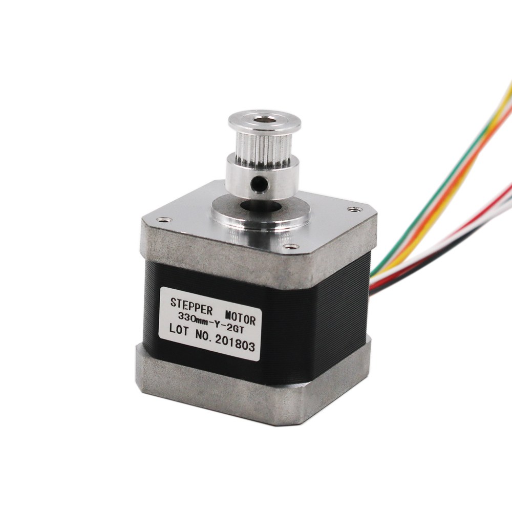
NEMA 17 stepper motor with 20T MXL gear, 0.36 Nm torque

How to Upgrade a 3D Printer with TMC2208 or TMC2209

Swap each A4988 driver for a TMC2208 or TMC2209 module to quiet a 3D printer. The modules are StepStick drop-in replacements for A4988 sockets, including RAMPS 1.4 boards. They run at 5.5 to 28V with up to 256-subdivision microstepping. Fit one module per axis motor, set the current, and print a test cube.

Nema 17 stepper motor 0.36Nm with 20T MXL gear
Nema 17 stepper motor with 0.36Nm holding torque and a 20T MXL gear installed.

Quick facts

Fact Value
TMC2208 $7.56 per module
TMC2209 $8.61 per module
TMC2130 $14.91 per module
ATD5833 $7.56 per module
Supply 5.5 to 28V
Microstepping Up to 256-subdivision
Size and weight 20 by 15 mm, about 6 g

Why do TMC drivers run quieter?

The modules divide each full step into up to 256 subdivisions, which smooths the motion and cuts the noise of full-step driving.

The listing describes the modules as silent drivers with quiet, smooth motion for 3D printers, CNC machines, and robotics builds.

Each module measures 20 by 15 mm, weighs about 6 g, and ships with a heatsink included.

Which chip should you pick?

The listing offers four driver chips on the same module: TMC2208, TMC2209, TMC2130, and ATD5833, with one module per order.

The TMC2208 costs $7.56, the TMC2209 costs $8.61, the TMC2130 costs $14.91, and the ATD5833 costs $7.56.

All four share the StepStick form factor and the 5.5 to 28V supply range, so the choice is the chip, not the board.

Which motors pair with these drivers?

NEMA 17 motors suit 3D printer axes, with a 1.8 degree step angle that gives 200 steps per revolution.

The single NEMA 17 motor holds 0.36 Nm at 1.2A per phase, with a 20T MXL gear installed for belt drives.

The 4-pack of NEMA 17 motors holds 0.22 Nm each at 1.3A per phase, which covers a full printer axis set in one order.

How do you install them?

Power off and unplug the printer, then note the orientation of every old driver before you pull it.

A driver inserted backwards dies instantly, so match the enable pin side on the new module to the old one.

Set the current with the onboard potentiometer and a meter before you run a print, and fit the included heatsink.

What did we check on the bench?

We checked the listing states 5.5 to 28V, 256-subdivision, StepStick form factor, RAMPS 1.4 fit, and a heatsink included.

We counted 4 images on the TMC module listing, 2 on the single NEMA 17 listing, and 3 on the NEMA 17 4-pack listing.

We matched every price here to the live store price on November 12, 2026, including all four chip variants.

How do you swap the drivers?

  1. Power off the printer, unplug it, and note the orientation of each old driver.
  2. Pull one old driver, keeping the rest in place so a mistake stays easy to find.
  3. Set the new module current with the onboard potentiometer and a meter.
  4. Fit the included heatsink, then insert the module in the same orientation as the old driver.
  5. Power up, move the axis slowly, and print a small test cube before a long print.

Parts that fit this guide

Shipped fast and securely from our secure facility in New York, providing fast, high quality USA shipping.

TMC2208 / TMC2209 Silent Stepper Motor Driver Module, 5.5-28V, 256-Subdivision ($7.56)

TMC2208 / TMC2209 silent stepper motor driver module at $7.56. StepStick drop-in for A4988 sockets, 5.5 to 28V, 256-subdivision. Choose TMC2208 at $7.56, TMC2209 at $8.61, TMC2130 at $14.91, or ATD5833 at $7.56.

Nema 17 Stepper Motor, 0.36Nm, 1.2A, with 20T MXL Gear ($9.99)

Nema 17 stepper motor at $9.99. 0.36Nm holding torque, 1.2A per phase, 1.8 degree step angle, 20T MXL gear installed.

Nema 17 Stepper Motor, 0.22Nm, 1.3A, 4-Pack ($27.99)

Nema 17 stepper motor 4-pack at $27.99. 0.22Nm each, 1.3A per phase, 1.8 degree step angle, 12 to 24V suggested input.

Related parts: A4988 Stepper Motor Driver Module with Heat Sink, Single: A4988 stepper motor driver module, the driver these TMC modules replace in StepStick sockets.

Shop the full range: Stepper Motors & Drivers at Quality RC Parts. See also: Related guide.

Frequently asked questions

How many modules does a printer need?

One module per axis motor. The listing sells one module per order, so order one for each axis you plan to upgrade.

Do the modules fit a RAMPS 1.4 board?

Yes. The listing states the modules are drop-in replacements for A4988 sockets, including RAMPS 1.4 and similar boards.

Is a heatsink included?

Yes. The listing states a heatsink is included with each module. Fit it before you run a print.

What supply voltage do the modules take?

The listing states a wide 5.5 to 28V supply range, with an operating temperature of -40 to 80C.

Sources

Last updated: November 12, 2026.

Posted on

How to Build a Wildlife Camera with an ESP32-S3-CAM

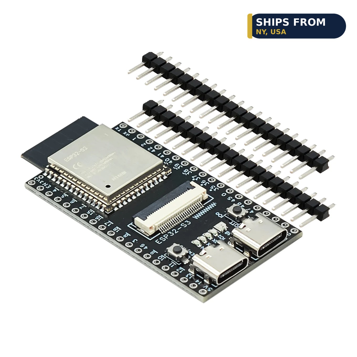
ESP32-S3-CAM N16R8 development board with camera options

How to Build a Wildlife Camera with an ESP32-S3-CAM

Build the camera from an ESP32-S3-CAM board, a camera module, and a PIR sensor. The board alone costs $11.97 with 16MB of flash and 8MB of PSRAM. The OV5640 camera version costs $29.99 and gives 5MP stills. The PIR sensor wakes the camera when an animal crosses its 7 m range.

Quick facts

Fact Value
S3-CAM board only $11.97, 16MB flash, 8MB PSRAM
S3-CAM + OV2640 $23.12, 2MP stills
S3-CAM + OV5640 $29.99, 5MP stills
PIR sensor Up to 7 m range, under 120 degree cone
PIR delay 0.3 to 18 sec adjustable, 5 to 20V
Ports Dual USB-C, TF card slot

Which camera module suits wildlife photos?

The OV5640 gives 5MP stills for $29.99 with the board.

It suits stills where detail matters, such as fur and feathers. The OV2640 gives 2MP stills for $23.12 and suits fast video.

Both cameras fit the same board connector. Pick the OV5640 for photos and the OV2640 for video clips.

How does the PIR sensor trigger the camera?

The PIR sensor sees motion up to 7 m away inside a cone under 120 degrees.

It runs on 5V to 20V and holds its output for 0.3 to 18 sec. Set a long delay for video and a short delay for stills.

The sensor costs $4.99. Wire its output to a GPIO pin and wake the camera on a rising edge.

How do you store photos without a network?

Save stills to the TF card slot on the board.

A card keeps photos when the network drops. The 16MB of flash holds the sketch and camera settings.

The 8MB of PSRAM holds each frame while the board sends it. Check the card after each field trip.

How do you mount the camera outside?

Mount the camera where the trail crosses the PIR cone.

The sensor sees up to 7 m, so a trail 3 to 5 m out sits well inside its range. Aim the cone across the trail, not along it.

Mount the board in a weatherproof case with the lens clear. Test the trigger at 2 m first, then move to the trail.

How is the wildlife camera different from a security camera?

The wildlife camera uses the 5MP OV5640 for stills, while a security camera uses the 2MP OV2640 for video.

The OV5640 version costs $29.99, and the OV2640 version costs $23.12. Both run on the same $11.97 board.

The older ESP32-CAM board costs $25.99 with an OV2640 camera and 4MB of PSRAM. Pick it when the fitted board suits the job.

How the options compare

S3-CAM option Camera Flash and PSRAM Price
Board only No camera 16MB flash, 8MB PSRAM $11.97
With OV2640 OV2640 2MP 16MB flash, 8MB PSRAM $23.12
With OV5640 OV5640 5MP 16MB flash, 8MB PSRAM $29.99
5-pack, board only No camera 16MB flash, 8MB PSRAM $46.17
10-pack, OV2640 OV2640 2MP 16MB flash, 8MB PSRAM $137.07

How do you build the wildlife camera?

  1. Pick the board-only version or a camera version at checkout.
  2. Fit the camera module on the board connector if it ships loose.
  3. Connect the board to a stable 5V supply over USB-C.
  4. Load the camera sketch from the Arduino-ESP32 examples.
  5. Wire the PIR sensor output to a GPIO pin.
  6. Mount the camera on the trail and test the trigger at 2 m first.

Parts that fit this guide

In-stock parts ship from the New York, USA warehouse in 1-2 business days. Prices below are the live store prices we verified on November 10, 2026.

ESP32-S3-CAM Development Board N16R8 – Board, OV2640 or OV5640 Camera, 1/5/10-Pack ($11.97)

ESP32-S3-CAM board at $11.97 for the board only. It carries 16MB of flash and 8MB of PSRAM, with OV2640 or OV5640 camera options.

HC-SR501 PIR Motion Sensor Module ($4.99)

PIR sensor at $4.99. It sees motion up to 7 m away, with a 0.3 to 18 sec delay.

ESP32-CAM Development Board with OV2640 Camera Module, 4MB PSRAM ($25.99)

ESP32-CAM board at $25.99. It ships with an OV2640 camera module, 4MB of PSRAM, WiFi, Bluetooth, and a TF card slot.

Shop the full range: ESP32 and ESP8266 at Quality RC Parts. See also: Related guide.

Frequently asked questions

Which camera gives sharper wildlife photos?

The OV5640 at 5MP. The S3-CAM board with the OV5640 camera costs $29.99.

Does the $11.97 board include a camera?

No. The $11.97 option is the board only. The OV2640 version costs $23.12, and the OV5640 version costs $29.99.

How far does the PIR sensor see?

Up to 7 m inside a cone under 120 degrees. Mount it where the trail crosses the cone.

Can the camera save photos without WiFi?

Yes. The board has a TF card slot, so stills land on the card when the network drops.

Sources

Last updated: November 10, 2026.

Posted on

How to Build a WiFi Security Camera with ESP32-CAM

ESP32-CAM development board with OV2640 camera module

How to Build a WiFi Security Camera with ESP32-CAM

Build the camera from an ESP32-CAM board, an OV2640 camera module, and a PIR sensor. The board streams video over WiFi and costs $25.99 with the camera fitted. The PIR sensor wakes the camera when motion crosses its 7 m range. The sensor costs $4.99 and holds its output for 0.3 to 18 sec.

Quick facts

Fact Value
ESP32-CAM board $25.99, OV2640 2MP, 4MB PSRAM
ESP32-S3-CAM board $11.97 board only, 16MB flash, 8MB PSRAM
PIR sensor Up to 7 m range, under 120 degree cone
PIR delay 0.3 to 18 sec adjustable, 5 to 20V
Storage TF card slot on both boards
Wireless WiFi and Bluetooth on both boards

What does the ESP32-CAM board include?

The board ships with an OV2640 camera and 4MB of PSRAM for $25.99.

It gives WiFi and Bluetooth on one chip. That lets you stream video to a phone or a laptop with no extra radio.

It uses a micro USB port for power and programming. A TF card slot stores stills when the network drops.

How does the PIR sensor wake the camera?

The PIR sensor sees motion up to 7 m away inside a cone under 120 degrees.

It runs on 5V to 20V and holds its output for 0.3 to 18 sec. Set a short delay for stills and a long delay for video.

The sensor costs $4.99. Wire its output to a GPIO pin and wake the camera on a rising edge.

Should you pick the ESP32-S3-CAM instead?

Pick the S3-CAM board at $11.97 when you need 16MB of flash and 8MB of PSRAM.

Add an OV2640 camera for $23.12 in total, or an OV5640 camera for $29.99 in total. The OV5640 gives 5MP stills for sharper photos.

The S3-CAM uses dual USB-C ports and the same TF card slot. Pick the older ESP32-CAM when the $25.99 fitted board suits the job.

How do you power the camera and sensor?

Power the board from a stable 5V supply over its micro USB port.

A weak supply drops the video feed when the camera captures a frame. Use a dedicated 5V supply, not a shared hub.

The PIR sensor runs on 5V to 20V, so the same 5V supply feeds it. Join the grounds of the board and the sensor.

How do you view the video stream?

The board serves its video stream over WiFi to a browser.

Open the stream address on a phone or a laptop on the same network. The 4MB of PSRAM holds each frame while the board sends it.

Test the stream at 2 m from the router first. Move the camera farther only after the near stream runs clean.

How the options compare

Camera option Camera Flash and PSRAM Price
ESP32-CAM OV2640 2MP included Not listed flash, 4MB PSRAM $25.99
ESP32-S3-CAM board No camera 16MB flash, 8MB PSRAM $11.97
S3-CAM + OV2640 OV2640 2MP 16MB flash, 8MB PSRAM $23.12
S3-CAM + OV5640 OV5640 5MP 16MB flash, 8MB PSRAM $29.99
PIR sensor, 2-pack Motion trigger, up to 7 m Not listed $4.99

How do you build the WiFi security camera?

  1. Fit the OV2640 camera module on the ESP32-CAM board connector.
  2. Connect the board to a stable 5V supply over micro USB.
  3. Load the camera sketch from the Arduino-ESP32 examples.
  4. Join the board to your WiFi network with your network name and password.
  5. Wire the PIR sensor output to a GPIO pin.
  6. Open the stream address in a browser and test the motion trigger.

Parts that fit this guide

In-stock parts ship from the New York, USA warehouse in 1-2 business days. Prices below are the live store prices we verified on November 10, 2026.

ESP32-CAM Development Board with OV2640 Camera Module, 4MB PSRAM ($25.99)

ESP32-CAM board at $25.99. It ships with an OV2640 camera module, 4MB of PSRAM, WiFi, Bluetooth, and a TF card slot.

ESP32-S3-CAM Development Board N16R8 – Board, OV2640 or OV5640 Camera, 1/5/10-Pack ($11.97)

ESP32-S3-CAM board at $11.97 for the board only. It carries 16MB of flash and 8MB of PSRAM, with OV2640 or OV5640 camera options.

HC-SR501 PIR Motion Sensor Module ($4.99)

PIR sensor at $4.99. It sees motion up to 7 m away, with a 0.3 to 18 sec delay.

Shop the full range: ESP32 and ESP8266 at Quality RC Parts. See also: Related guide.

Frequently asked questions

Does the ESP32-CAM board include a camera?

Yes. The $25.99 board ships with an OV2640 camera module and 4MB of PSRAM.

How far does the PIR sensor see?

Up to 7 m inside a cone under 120 degrees. Mount it where the subject crosses the cone.

Can the camera save photos without a network?

Yes. Both boards in this guide have a TF card slot for stills and video storage.

Should I pick the S3-CAM board instead?

Pick it at $11.97 when you need 16MB of flash and 8MB of PSRAM. Add an OV2640 camera for $23.12 in total.

Sources

Last updated: November 10, 2026.

Posted on

How to Build an Obstacle Avoidance Robot Car with Arduino

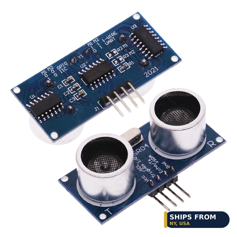
HC-SR04 ultrasonic ranging sensor module for Arduino

How to Build an Obstacle Avoidance Robot Car with Arduino

Build the car around an Arduino UNO, an HC-SR04 ultrasonic sensor, and an L298N motor driver. The sensor measures 2 to 450 cm ahead, and the driver runs 2 DC motors at 2A per bridge. The UNO R3 board costs $19.99. A TT motor set with 65mm wheels costs $9.63 and gives 800 gf cm of torque.

Quick facts

Fact Value
HC-SR04 sensor 2 to 450 cm range, 0.3 cm precision, 5V
L298N driver 5 to 35V, 2A per bridge, built-in 5V regulator
UNO R3 board ATmega328P, 16MHz, 14 digital pins
TT motor set 3 to 6V DC, 1:48 gear ratio, 800 gf cm
IR sensor 2 to 30 cm adjustable, 35 degree angle
TCRT5000 sensor 1 to 25 mm adjustable, 4-pack

How does the HC-SR04 sensor measure distance?

The sensor sends a sound pulse and times its echo over 2 to 450 cm.

It measures with 0.3 cm precision on 5V. That precision suits a car that must stop before it hits a wall.

The module costs from $4.01, with a module-only option at $4.49. Wire its trigger and echo pins to 2 digital pins on the UNO.

Which motor driver runs the car wheels?

The L298N driver runs 2 DC motors at 2A per bridge.

It takes 5 to 35V and drives 2 DC motors or 1 stepper motor. A built-in 5V regulator feeds the logic side.

One driver costs $7.17, a 2-pack costs $12.65, and a 4-pack costs $25.99. Keep one spare for the next build.

Which motors and wheels move the car?

The TT motor set gives 2 motors and 2 wheels for $9.63.

Each motor runs on 3 to 6V DC with a 1:48 gear ratio. It gives 800 gf cm of torque through the gearbox.

The 65mm wheels fit the motor shafts with no extra adapter. Mount one motor on each side for a 2-wheel drive car.

How do IR and line sensors add to the car?

The IR sensor stops the car 2 to 30 cm from an object.

It uses a 35 degree angle and an LM393 comparator on 3.3 to 5V. The 5-pack costs $6.20, and the 10-pack costs $8.85.

The TCRT5000 tracks a line at 1 to 25 mm with a digital output. A single sensor costs $2.29 for a line-following car.

How do you power the car?

Power the motors from a battery pack through the L298N driver.

The driver takes 5 to 35V, so a 6V or 12V pack suits the car. The UNO board takes power over USB or its 5V pin.

Join the grounds of the motor supply and the UNO board. A missing common ground makes the motors ignore commands.

The JST-XH kit costs $12.72 and holds 500 housings, terminals, and pin headers. It builds the leads the car needs.

How the options compare

Part Key spec Price
HC-SR04 sensor 2 to 450 cm, 0.3 cm precision, 5V From $4.01
IR obstacle sensor 2 to 30 cm, 35 degree angle $6.20, 5-pack
TCRT5000 sensor 1 to 25 mm, digital output $2.29
L298N driver 5 to 35V, 2A per bridge $7.17
TT motor set 3 to 6V, 1:48, 800 gf cm $9.63
UNO R3 board ATmega328P, 16MHz, 14 digital pins $19.99

How do you build the obstacle avoidance robot car?

  1. Mount the TT motors and 65mm wheels on the chassis.
  2. Fit the HC-SR04 sensor on the front of the car.
  3. Wire the L298N driver to the motors and the battery pack.
  4. Connect the sensor trigger and echo pins to the UNO board.
  5. Load the sketch that stops the car when the sensor reads under 30 cm.
  6. Test the car on the floor and tune the stop distance.

Parts that fit this guide

In-stock parts ship from the New York, USA warehouse in 1-2 business days. Prices below are the live store prices we verified on November 10, 2026.

HC-SR04 Ultrasonic Ranging Sensor Module for Arduino, 2-450cm, with Mounting Bracket Options ($4.01)

HC-SR04 sensor at $4.01 listed, with a module-only option at $4.49. It measures 2 to 450 cm with 0.3 cm precision on 5V.

L298N Dual H-Bridge Motor Driver Module for Arduino, DC / Stepper, 5-35V, 2A ($7.17)

L298N driver at $7.17 for 1 piece. It runs 2 DC motors or 1 stepper motor at 2A per bridge on 5 to 35V.

TT Motor 130 Gear Motor + 65mm Wheel Set, 2 Motors + 2 Wheels, 3-6V DC, for Arduino Smart Car Robot ($9.63)

TT motor set at $9.63. It gives 2 motors and 2 wheels on 3 to 6V DC, with a 1:48 gear ratio and 800 gf cm of torque.

ELEGOO UNO R3 Microcontroller Board, ATmega328P + ATmega16U2, with USB Cable ($19.99)

ELEGOO UNO R3 board at $19.99 with a USB cable included. It carries an ATmega328P chip, runs at 16MHz, and gives 14 digital pins and 6 analog inputs.

IR Infrared Obstacle Avoidance Sensor Module, 5-Pack / 10-Pack ($6.20)

IR obstacle sensor at $6.20 for a 5-pack. It detects 2 to 30 cm at a 35 degree angle on 3.3 to 5V.

Shop the full range: Robot Chassis and Kits at Quality RC Parts. See also: Related guide.

Frequently asked questions

How far ahead does the HC-SR04 sensor see?

It measures 2 to 450 cm with 0.3 cm precision on 5V. The module costs from $4.01.

What motor driver does the car need?

The L298N driver at $7.17. It runs 2 DC motors at 2A per bridge on 5 to 35V.

Can the car follow a line too?

Yes. The TCRT5000 sensor tracks a line at 1 to 25 mm, and a single sensor costs $2.29.

How do I power the car motors and the UNO board?

Power the motors through the L298N driver from a battery pack, and join the grounds of the motor supply and the UNO board.

Sources

Last updated: November 10, 2026.

Posted on

How to Build a Pan-Tilt Camera with ESP32-CAM Servos

ESP32-CAM development board with OV2640 camera module

How to Build a Pan-Tilt Camera with ESP32-CAM Servos

Build a pan-tilt camera with an ESP32-CAM board and two micro servos. One servo pans the camera left and right, and one tilts it up and down. A PIR sensor wakes the camera when motion crosses its 7m range. The ESP32-S3-CAM board costs $11.97 and carries 16MB of flash and 8MB of PSRAM.

Quick facts

Fact Value
ESP32-S3-CAM board $11.97, 16MB flash, 8MB PSRAM
ESP32-CAM board $25.99, OV2640 camera, 4MB PSRAM
Pan and tilt servos SG92R, 2.5 kg/cm at 4.8V, $8.00
PIR sensor Up to 7m range, 0.3 to 18 sec delay, $4.99
Camera options OV2640 2MP or OV5640 5MP
Servo horn set $8.37, 4-point aluminum 2-pack

Which board fits a pan-tilt camera?

The ESP32-S3-CAM suits a new build with more memory. It carries 16MB of flash and 8MB of PSRAM for $11.97 as a board only.

The ESP32-CAM suits a simple build with a fixed camera. It costs $25.99 with an OV2640 camera module and 4MB of PSRAM.

Pick the OV5640 5MP camera for sharper stills. Pick the OV2640 2MP camera for faster video streaming.

Which micro servos move a small camera?

A camera board weighs little, so a micro servo has torque to spare. The SG92R gives 2.5 kg/cm at 4.8V and costs $8.00.

Use one SG92R for pan and one for tilt. Both servos center the same way, so one test routine covers the pair.

Fit a 4-point aluminum horn on each servo spline. The $8.37 set is a 2-pack with a ball link for the camera plate.

How do you wire servos to the ESP32-CAM?

Wire each servo signal lead to a free GPIO pin on the board. The ESP32 LEDC driver gives 16 PWM channels for servo control.

Power the servos from a 5V to 6V supply, not from the board. A camera board cannot feed two servos under load.

Join the grounds of the servo supply and the board. A missing common ground makes servos jitter and ignore commands.

How does the PIR sensor trigger the camera?

The HC-SR501 PIR sensor watches for body heat in its cone. It sees motion up to 7m away inside a cone under 120 degrees.

It runs on 5V to 20V and holds its output for 0.3 to 18 sec. Set a short delay for stills and a long delay for video.

Wire its output to a GPIO pin and wake the camera on a rising edge. The sensor costs $4.99.

How do you test pan and tilt travel?

Center both servos before you fit the camera plate. A servo that starts off center loses travel on one side.

Move the pan servo through its full range and watch the camera. It should sweep smooth with no binding at either end.

Set software limits just inside the hard stops. A servo that pushes against a stop will draw stall current and heat up.

How the options compare

Part Role Key spec Price
ESP32-S3-CAM board Camera controller 16MB flash, 8MB PSRAM $11.97
ESP32-CAM board Camera controller OV2640 camera, 4MB PSRAM $25.99
SG92R servo Pan and tilt 2.5 kg/cm at 4.8V $8.00
PIR sensor Motion trigger Up to 7m range $4.99
4-point horn set Camera plate link Aluminum 2-pack $8.37

How do you build the pan-tilt camera?

  1. Center both SG92R servos and fit their horns at 90 degrees.
  2. Mount the pan servo to the base and the tilt servo to the plate.
  3. Wire the servo signals to free GPIO pins on the board.
  4. Connect the servos to a 5V to 6V supply with a common ground.
  5. Wire the PIR sensor output to a GPIO pin.
  6. Load the camera sketch and test pan, tilt, and motion trigger.

Parts that fit this guide

In-stock parts ship from the New York, USA warehouse in 1-2 business days. Prices below are the live store prices we verified on November 10, 2026.

ESP32-S3-CAM Development Board N16R8 – Board, OV2640 or OV5640 Camera, 1/5/10-Pack ($11.97)

ESP32-S3-CAM board at $11.97 for the board only. It carries 16MB of flash and 8MB of PSRAM.

ESP32-CAM Development Board with OV2640 Camera Module, 4MB PSRAM ($25.99)

ESP32-CAM board at $25.99. It ships with an OV2640 camera module and 4MB of PSRAM.

SG92R Analog Plastic Composite Gear Micro Servo ($8.00)

Micro servo at $8.00. It gives 2.5 kg/cm of torque at 4.8V for pan and tilt.

HC-SR501 PIR Motion Sensor Module ($4.99)

PIR sensor at $4.99. It sees motion up to 7m away.

4-Point Aluminum Servo Arm Horn Set with Rudder Angle Ball Link, RC Aircraft, 2-Pack ($8.37)

Aluminum horn set at $8.37. It is a 2-pack with a ball link for the camera plate.

Shop the full range: ESP32 and ESP8266 at Quality RC Parts. See also: Related guide.

Frequently asked questions

Do I need two servos for a pan-tilt camera?

Yes. One servo pans the camera left and right, and one tilts it up and down.

Which ESP32-CAM board should I pick?

Pick the ESP32-S3-CAM for more memory at $11.97. Pick the ESP32-CAM for a simple build at $25.99 with camera included.

How far does the PIR sensor see?

Up to 7m inside a cone under 120 degrees. Mount it where the subject crosses the cone, not where it walks straight at it.

Can I power the servos from the ESP32-CAM board?

No. Power them from a separate 5V to 6V supply with a common ground, or the servos will brown out the board.

Sources

Last updated: November 10, 2026.

Posted on

How to Build a Robot Arm with ESP32 and Servo Motors

ESP32 DevKit V1 30-pin WROOM-32 development board

How to Build a Robot Arm with ESP32 and Servo Motors

Build a robot arm with an ESP32 board, one servo per joint, and rigid M3 hardware. The ESP32 drives each servo with a PWM signal, and a 12 kg.cm servo holds the base joint under load. A display shows joint angles while you test. The ESP32 DevKit V1 costs $11.99 and carries WiFi and Bluetooth.

Quick facts

Fact Value
ESP32 DevKit V1 $11.99, 30-pin WROOM-32, WiFi and Bluetooth
Base joint servo 12 kg.cm at 6V, SPT4412LV, $53.99
Heavy servo option 60 to 160 kg, DSSERVO, $53.24 to $56.69
OLED display $7.49, 128 by 64 pixels, I2C
M3 hardware kit $10.56, 150 pieces, 8 to 25mm
Servo horn set $8.37, 4-point aluminum 2-pack

Which servos does a robot arm need?

A robot arm needs one servo per joint, with the most torque at the base. The base joint carries the whole arm, so it needs the strongest servo.

The SPT4412LV gives 12 kg.cm of stall torque at 6V for the base joint. It moves in 0.09 sec per 60 degrees at 6V.

The DSSERVO range gives 60 to 160 kg for a large arm base. Servo options run $53.24 to $56.69 by torque class and travel.

How does the ESP32 drive the servos?

The ESP32 drives each servo with a PWM signal on a GPIO pin. A 50 Hz signal with a 1 to 2 ms pulse sets the servo angle.

The Espressif LEDC driver gives 16 PWM channels on the ESP32. That covers a 4 joint arm with channels to spare.

The Arduino Servo library wraps the same PWM setup in simple calls. Use servo.attach on a pin, then servo.write to set the angle.

How do you power servos and the ESP32?

Power the servos from a separate 5V to 6V supply, not from the ESP32 board. Servos draw far more current than a board pin can give.

Join the grounds of the servo supply and the ESP32. A missing common ground makes servos jitter and ignore commands.

The MG996R datasheet lists 1400mA of stall current for one standard servo. Size the supply for stall current across all joints.

How do you mount the arm joints?

Rigid joints need bolts that match the arm plates. The M3 kit in this guide costs $10.56 and holds 150 pieces from 8 to 25mm.

Fit a 4-point aluminum horn on each servo spline. The $8.37 set is a 2-pack with a ball link for the arm rods.

Tighten each joint until it holds, then back off a quarter turn. A joint that binds will stall its servo and drain the supply.

How do you add a display to show joint angles?

A small OLED shows each joint angle while you test the arm. The $7.49 display in this guide measures 0.96 inch with 128 by 64 pixels.

It runs on I2C with 4 pins and takes 3.3V to 5V. That suits the ESP32 DevKit V1 without extra level shifting.

Update the display once per loop after you move the servos. A display that updates too fast will flicker and hide the numbers.

How the options compare

Part Role Key spec Price
ESP32 DevKit V1 Controller 30-pin WROOM-32, WiFi and Bluetooth $11.99
SPT4412LV servo Base joint 12 kg.cm at 6V $53.99
DSSERVO range Heavy base joint 60 to 160 kg $53.24 to $56.69
4-point horn set Joint links Aluminum 2-pack $8.37
OLED display Angle readout 128 by 64 pixels, I2C $7.49
M3 hardware kit Joint bolts 150 pieces, 8 to 25mm $10.56

How do you build the robot arm?

  1. Mount the base servo and fit its horn at center.
  2. Assemble the arm plates with M3 bolts and check each joint.
  3. Wire each servo signal pin to a separate ESP32 GPIO pin.
  4. Connect the servos to a 5V to 6V supply with a common ground.
  5. Load the test sketch and move each joint through its range.
  6. Fit the OLED display and show the joint angles while you test.

Parts that fit this guide

In-stock parts ship from the New York, USA warehouse in 1-2 business days. Prices below are the live store prices we verified on November 10, 2026.

ESP32 DevKit V1 Development Board, 30-Pin WROOM-32, WiFi + Bluetooth ($11.99)

ESP32 DevKit V1 at $11.99. It is a 30-pin WROOM-32 board with WiFi and Bluetooth.

Dilwe SPT4412LV 12KG Digital Servo Large Torsion Metal Gear for 1:10 RC Drift Car ($53.99)

Base joint servo at $53.99. It gives 12 kg.cm of stall torque at 6V.

DSSERVO High Torque Waterproof Digital Servo 60KG / 80KG / 150KG / 160KG for 1/5 1/6 Redcat HPI Baja 5B ($2.25)

Heavy servo option, listed from $53.24 to $56.69 by torque class. The $2.25 option is a hardware set only, not a servo.

4-Point Aluminum Servo Arm Horn Set with Rudder Angle Ball Link, RC Aircraft, 2-Pack ($8.37)

Aluminum horn set at $8.37. It is a 2-pack with a ball link for arm joints.

0.96 Inch OLED Display Module, SSD1306, I2C, 128×64, for Arduino / ESP32 / ESP8266 ($7.49)

OLED display at $7.49. It measures 0.96 inch with 128 by 64 pixels on I2C.

M3 Stainless Steel Hex Socket Screw, Bolt & Nut Assortment Kit, 150-Piece (8-25mm) ($10.56)

M3 hardware kit at $10.56. It holds 150 pieces from 8 to 25mm in an organizer box.

Shop the full range: Robot Arms at Quality RC Parts. See also: Related guide.

Frequently asked questions

How many servos does a robot arm need?

One per joint. A 4 joint arm needs 4 servos, with the strongest at the base.

Can an ESP32 drive 4 servos at once?

Yes. The LEDC driver gives 16 PWM channels, so 4 servos leave channels to spare.

Why do my servos jitter when the ESP32 boots?

The grounds are not joined, or the supply is too weak. Join the grounds and size the supply for stall current.

What torque does the base joint need?

At least 12 kg.cm for a small arm. The SPT4412LV gives 12 kg.cm at 6V and costs $53.99.

Sources

Last updated: November 10, 2026.

Posted on

How to Use a 0.96 Inch SSD1306 OLED Display

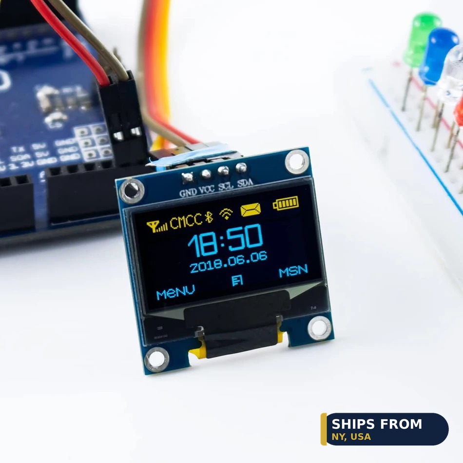
0.96 inch SSD1306 OLED display module with 128 by 64 pixels

How to Use a 0.96 Inch SSD1306 OLED Display

Connect a 0.96 inch SSD1306 OLED display to your board over I2C with 4 wires. The module shows 128 by 64 pixels and runs on 3.3V to 5V. Wire GND, VCC, SCL, and SDA, then load the Adafruit SSD1306 library. The blue module costs $7.49. A DHT22 sensor adds temperature and humidity readings to the screen for $4.99.

Quick facts

Fact Value
Display 0.96 inch, 128 by 64 pixels
Driver SSD1306, I2C interface
Pins 4 pins: GND, VCC, SCL, SDA
Voltage 3.3V to 5V
Blue module $7.49 for blue, white, and yellow-blue
Sensor pair DHT22 $4.99, 0 to 100% RH

What pins does the SSD1306 OLED display use?

The display uses 4 pins: GND, VCC, SCL, and SDA.

It runs on I2C, so 2 data lines carry the display traffic. SCL clocks the data, and SDA carries it.

The module takes 3.3V to 5V, so it suits Arduino and ESP32 boards with no extra level shifting.

How do you wire the OLED display to an Arduino UNO?

Wire the display to the UNO I2C pins with 4 short wires.

Connect SDA to A4 and SCL to A5 on the UNO R3 board. The UNO R3 costs $19.99 and gives 14 digital pins and 6 analog inputs.

Power the display from the 5V pin and ground from GND. Keep the wires short to avoid noise on the I2C lines.

How do you wire the OLED display to an ESP32?

Wire the display to the ESP32 I2C pins at 3.3V.

The ESP32 DevKit V1 costs $15.99 for the Type-C board and gives 30 pins. Use the default I2C pins in the sketch, or set any 2 GPIO pins as SDA and SCL.

The display takes 3.3V to 5V, so the ESP32 3.3V pin works. The SuperMini board also suits the display, with prices from $9.99.

Which OLED color should you pick?

Pick any color at $7.49. All three colors cost the same.

The white and yellow-blue modules also cost $7.49. All 3 give the same 128 by 64 pixels on the same 0.96 inch panel.

Pick yellow-blue when the top lines must stand out from the rest. Pick white when the display must match a white case.

When does a TFT display fit better than an OLED?

Pick a TFT display when the project needs color or a larger screen.

The TFT module runs from $5.83 for 0.96 inch to $10.92 for 2.8 inch. It shows 65K colors over SPI, while the OLED shows one color.

The OLED still wins for crisp text at low power. Pick the OLED for readouts and the TFT for graphs and gauges.

How do you show sensor readings on the OLED?

Read the sensor in the sketch, then draw the value on the display.

The DHT22 sensor reads 0 to 100% relative humidity and -40 to 80C. It costs $4.99 and runs on 3.3V to 5.5V.

Update the display once per loop so the numbers stay readable. Read the DHT22 once per 2 sec, since the sensor needs time between reads.

How the options compare

Display Size Interface Colors Price
OLED, blue 0.96 inch, 128 by 64 pixels I2C, 4 pins 1 color $7.49
OLED, white 0.96 inch, 128 by 64 pixels I2C, 4 pins 1 color $7.49
OLED, yellow-blue 0.96 inch, 128 by 64 pixels I2C, 4 pins 1 color $7.49
TFT LCD, 0.96 inch 0.96 inch SPI 65K colors $5.83
TFT LCD, 2.0 inch 2.0 inch SPI 65K colors $9.72
TFT LCD, 2.8 inch 2.8 inch SPI 65K colors $10.92
TM1637 7-segment 0.56 inch, 4 digits CLK and DIO, 2 pins 1 color $6.21

How do you wire and test the OLED display?

  1. Connect GND and VCC to the board ground and 3.3V or 5V pins.
  2. Connect SCL and SDA to the board I2C pins.
  3. Install the Adafruit SSD1306 library in the Arduino IDE.
  4. Load the library example sketch for a 128 by 64 display.
  5. Check that the display shows the test pattern.
  6. Wire the DHT22 sensor and draw its readings on the display.

Parts that fit this guide

In-stock parts ship from the New York, USA warehouse in 1-2 business days. Prices below are the live store prices we verified on November 10, 2026.

0.96 Inch OLED Display Module, SSD1306, I2C, 128×64, for Arduino / ESP32 / ESP8266 ($7.49)

OLED display at $7.49 for blue. It measures 0.96 inch with 128 by 64 pixels on I2C, and takes 3.3V to 5V.

ELEGOO UNO R3 Microcontroller Board, ATmega328P + ATmega16U2, with USB Cable ($19.99)

ELEGOO UNO R3 board at $19.99 with a USB cable included. It carries an ATmega328P chip, runs at 16MHz, and gives 14 digital pins and 6 analog inputs.

DHT22 / AM2302 Digital Temperature & Humidity Sensor Module ($4.99)

DHT22 sensor at $4.99. It reads 0 to 100% relative humidity and -40 to 80C on 3.3V to 5.5V.

TFT LCD Display Module, IPS SPI, 0.96-2.8 inch, ST7735/ST7789/ILI9341 ($5.83)

TFT LCD display at $5.83 to $10.92 by size. It gives an IPS SPI display in 0.96 to 2.8 inch sizes with 65K colors.

Shop the full range: Displays at Quality RC Parts. See also: Related guide.

Frequently asked questions

How many pins does the OLED display need?

It needs 4 pins: GND, VCC, SCL, and SDA. It runs on I2C with 3.3V to 5V.

Does the display work with an Arduino UNO?

Yes. Wire SDA to A4 and SCL to A5 on the UNO R3 board, which costs $19.99.

Which OLED color costs the least?

The blue, white, and yellow-blue modules all cost $7.49.

Can the display show sensor readings?

Yes. The DHT22 sensor at $4.99 reads 0 to 100% relative humidity and -40 to 80C for the display.

Sources

Last updated: November 10, 2026.