
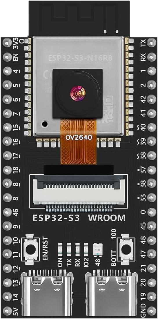
ESP32-S3-CAM GPIO Pinout, Complete: Camera, SD Card, and Free Pins
The ESP32-S3-CAM board gives you a camera, WiFi, and a lot of GPIO in one board, but the camera and SD card already claim a set of pins. If you wire a sensor, a servo, or an LED to one of those pins, the camera or the card stops working and the fault looks like bad code. This guide lists every camera pin and SD card pin on the ESP32-S3-CAM, shows the Arduino setup that matches them, and explains which pins are safe to use for your own parts.
The pinout below matches the ESP32-S3-EYE and Freenove pinout used by this board. In Arduino, select CAMERA_MODEL_ESP32S3_EYE and the camera driver uses these pins.
Camera pins
The camera uses a DVP parallel interface: a clock, two I2C lines for control, sync lines, a pixel clock, and eight data lines. Every pin in this table belongs to the camera. Do not connect anything else to these pins while the camera is in use.
| Signal | GPIO | What it does |
|---|---|---|
| XCLK | GPIO15 | Camera clock output from the ESP32-S3 |
| SIOD | GPIO4 | Camera control data, I2C SDA |
| SIOC | GPIO5 | Camera control clock, I2C SCL |
| VSYNC | GPIO6 | Frame sync, marks the start of a frame |
| HREF | GPIO7 | Line sync, marks valid pixel rows |
| PCLK | GPIO13 | Pixel clock, times each pixel |
| D0 | GPIO11 | Camera data bit 0 |
| D1 | GPIO9 | Camera data bit 1 |
| D2 | GPIO8 | Camera data bit 2 |
| D3 | GPIO10 | Camera data bit 3 |
| D4 | GPIO12 | Camera data bit 4 |
| D5 | GPIO18 | Camera data bit 5 |
| D6 | GPIO17 | Camera data bit 6 |
| D7 | GPIO16 | Camera data bit 7 |
| PWDN | -1 | Power down, not connected on this board |
| RESET | -1 | Camera reset, not connected on this board |
PWDN and RESET show as -1 because this board does not wire them to a GPIO. The camera powers up and resets without them, and your code should leave both set to -1 in the camera config.
SD card pins
The SD card runs in SDMMC 1-bit mode on three pins. These pins belong to the card while recording is active. Do not share them with other peripherals.
| Signal | GPIO | What it does |
|---|---|---|
| SD CLK | GPIO39 | SD card clock |
| SD CMD | GPIO38 | SD card command line |
| SD D0 | GPIO40 | SD card data line, 1-bit mode |
Arduino setup
In Arduino, use the CAMERA_MODEL_ESP32S3_EYE model. The model sets the pin numbers above, so you do not enter them by hand. A minimal camera config looks like this:
#define CAMERA_MODEL_ESP32S3_EYE
#include "camera_pins.h"
camera_config_t config;
config.pin_pwdn = -1;
config.pin_reset = -1;
config.pin_xclk = 15;
config.pin_siod = 4;
config.pin_sioc = 5;
config.pin_vsync = 6;
config.pin_href = 7;
config.pin_pclk = 13;
config.pin_d0 = 11;
config.pin_d1 = 9;
config.pin_d2 = 8;
config.pin_d3 = 10;
config.pin_d4 = 12;
config.pin_d5 = 18;
config.pin_d6 = 17;
config.pin_d7 = 16;
If your sketch uses a different camera model define, the camera will fail to start and the serial monitor will report a camera init failure. The pin numbers are the fix, not the camera module. Check the model define first when init fails.
Which pins are free for your own parts
The board exposes up to 45 GPIOs. The camera takes 14 pins and the SD card takes 3, which leaves the rest for your build. Pick a free GPIO for each peripheral you add, and keep it clear of the camera and SD tables above. A PIR sensor, a temperature sensor, an LED, or a servo signal line all go on free pins, never on camera or SD pins.
Two practical rules save most debugging time. First, wire and test the camera and SD card before you add any other peripheral, so a dead camera points at the camera and not at your wiring. Second, if you add a peripheral and the camera stops, check its pin against the two tables above before you touch the code. A shared pin is the most common cause.
Board basics that affect the pinout
The board runs an ESP32-S3 dual-core processor at up to 240MHz with WiFi and Bluetooth 5 LE. The OV2640 version carries 16MB flash in the N16R8 class, and the OV5640 version carries 16MB flash plus 8MB PSRAM. Two USB-C ports split OTG and serial duties, so the board plugs in and starts developing with no adapters needed. None of that changes the camera or SD pins, but it explains why the board can stream video and record to SD at the same time: the S3 has the memory and the USB bandwidth to do both.
Parts that fit this guide
Prices below are the live store prices verified November 19, 2026. In-stock parts ship from New York in 1-2 business days.
ESP32-S3 Development Board with OV2640 Camera, Dual-Core 240MHz, WiFi + Bluetooth 5 LE, 45 GPIOs ($22.99)
ESP32-S3 camera board with OV2640 2MP camera, dual-core 240MHz, 45 GPIOs, WiFi plus Bluetooth 5 LE, and USB OTG. The board this pinout covers.
ESP32-S3-N16R8 CAM Development Board with OV5640 Camera, Dual USB-C, WiFi + Bluetooth 5 ($22.99)
ESP32-S3-N16R8 CAM board with OV5640 5MP camera, 16MB flash, 8MB PSRAM, and dual USB-C. Same camera and SD pinout as the OV2640 version.
Shop the full range in the ESP32 and ESP8266 category at Quality RC Parts. See also: How to Use the ESP32-S3-CAM Board for Camera Projects and ESP32-S3-CAM vs ESP32-CAM board comparison.
Frequently asked questions
Which camera model do I select in Arduino?
Use CAMERA_MODEL_ESP32S3_EYE. It matches the pinout in this guide. A different model define gives the wrong pins and the camera will not start.
Why are PWDN and RESET set to -1?
This board does not wire camera power-down or reset to a GPIO. A value of -1 tells the driver there is no pin to control, and the camera still works.
Can I use GPIO15 for an LED?
No. GPIO15 is the camera clock. Anything else on a camera pin will break the camera while it is running.
Does the SD card use SPI or SDMMC?
SDMMC 1-bit mode, on GPIO39 for clock, GPIO38 for command, and GPIO40 for data.
Last updated: November 19, 2026.