
How to Read a Microcontroller Datasheet: Specs That Matter
Read a microcontroller datasheet in this order: absolute maximum ratings first, recommended operating conditions second, the pinout and pin function table third, and the electrical characteristics fourth. The single most important distinction is that absolute maximum ratings are stress limits that damage the chip when exceeded, while recommended operating conditions are the values the chip is guaranteed to work at.
Microcontroller datasheet: what is a datasheet and which document do you need?
A datasheet is the manufacturer document that defines a chip: its features, its pinout, its electrical limits, its timing and its package. It is the primary source for every spec in a project, and it outranks tutorials, forum posts and product listings. When two sources disagree, the datasheet wins.
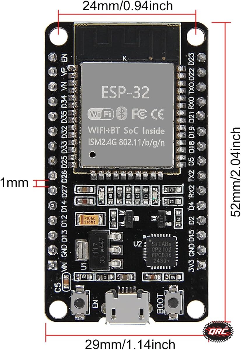
Three documents are often confused. The chip datasheet covers the silicon, such as the ESP32 or the RP2040. The module datasheet covers the module built on that chip, such as the ESP32-WROOM-32, including its antenna and its flash. The board schematic and board guide cover the development board, such as the ESP32 DevKit V1 or the Raspberry Pi Pico, including which chip pins reach the header and which are used by the USB chip or the flash. Chip pins and board pins differ, so read the board document for wiring and the chip datasheet for limits.
Check the revision and the date on the first page. The Espressif ESP32 Series Datasheet is at version 5.3 in the copy checked for this post. The ESP32-C3 Series Datasheet is at version 2.5. The Raspberry Pi RP2040 Datasheet is at build date 2025-02-20, build version 3184e62-clean. The Microchip ATmega328P datasheet is DS40002061B. A revision changes pin functions, current limits and errata, so a tutorial written against an old revision can be wrong for the chip you hold.
What are absolute maximum ratings?
Absolute maximum ratings are the stress limits beyond which the chip can be damaged. They are not operating conditions, and the chip is not guaranteed to work at them. The ATmega328P datasheet, DS40002061B, lists the absolute maximum supply voltage as 6.0 V, the voltage on any pin except RESET as minus 0.5 V to VCC plus 0.5 V, the DC current per I/O pin as 40 mA, and the DC current through the VCC and GND pins as 200 mA. Those numbers describe the point of damage, not a design target.
The recommended operating conditions for the same chip are stricter: the supply voltage is 1.8 V to 5.5 V, and the output voltages are guaranteed only up to 20 mA per pin. Design to 5.5 V and 20 mA, not to 6.0 V and 40 mA. A pin that survives 40 mA for a minute can still degrade, and a design that relies on an absolute maximum rating is a design that fails in the field.
The ESP32 datasheet follows the same pattern. Its GPIO pins are 3.3 V logic and are not 5 V tolerant, so a 5 V signal on an ESP32 GPIO pin exceeds the absolute maximum input voltage and can damage the pin. The RP2040 datasheet lists its I/O voltage range as 1.8 V to 3.3 V, with the same rule: a 5 V signal on a 3.3 V pin is out of spec. Read the absolute maximum input voltage row before you connect any signal, and use a level shifter when the voltages differ.
How do you read the pinout and pin function tables?
Start with the pinout diagram, which shows the physical package and the pin numbers. Then read the pin function table, which lists every pin, its name, its type and its alternate functions. A single GPIO pin on an ESP32 can serve as a digital input, a PWM output, an ADC input, an I2C line, a UART line or a touch input, depending on the configuration. The table tells you which functions each pin supports, and which pins support none of them.
Watch for four traps in the pin table. First, input only pins: GPIO 34 to 39 on the original ESP32 can read a signal but cannot drive one, and they have no internal pull-up or pull-down resistors. Second, strapping pins: GPIO 0, 2 and 15 on the ESP32, and GPIO 0, 2 and 15 on the ESP8266, must sit at specific levels at boot, so a sensor on those pins can stop the board from starting. Third, pins shared with flash memory: on many ESP32 boards, GPIO 6 to 11 connect to the flash chip and are not usable. Fourth, ADC pins shared with Wi-Fi: ADC2 pins on the ESP32 cannot be read while Wi-Fi runs.
On the RP2040, the pin function table shows that all 30 GPIO pins support PIO, and that GPIO 26 to 29 double as the four ADC inputs. On the ATmega328P, the table shows 23 programmable I/O lines, with 6 ADC inputs on the DIP package and 8 on the TQFP package, because ADC6 and ADC7 exist only on the surface mount package. That package difference is the kind of detail that only the datasheet gives you.
What do the electrical characteristics tell you?
The electrical characteristics section lists the numbers your circuit design depends on: input high and low voltage thresholds, output high and low voltages at a given current, input leakage current, pull-up resistor values and supply current in each sleep mode. Two rows matter most for a beginner build: the input high threshold, called VIH, and the input low threshold, called VIL.
On the ATmega328P at 5 V, the datasheet treats anything above 3.0 V, or 60 percent of VCC, as a definite high, and anything below 1.5 V, or 30 percent of VCC, as a definite low. The region between 1.5 V and 3.0 V is undefined, and a floating pin wanders through it. That is why a floating input reads randomly, and why a pull-up or pull-down resistor is needed. The ESP32 and RP2040 have their own VIH and VIL rows, and they differ, so check the row for your chip before you assume a 3.3 V signal is high enough for a 5 V input.
Current limits live in the same section. The ATmega328P guarantees its output voltages only up to 20 mA per pin, with a 200 mA total through the VCC and GND pins, and a 100 mA limit per pin group for sinking current. The ESP32 datasheet lists a recommended maximum of about 12 mA per GPIO pin for a reliable output level, with higher currents allowed only as absolute maximums. The RP2040 datasheet lists a 12 mA drive strength setting per pin. Never drive a motor, a relay or a solenoid directly from a GPIO pin on any of these chips: use a transistor or a driver board.
How do you use the ADC, PWM and peripheral sections?
Each peripheral has its own section with its own limits. The ADC section gives the resolution, the channel count, the reference voltage and the input range. The ESP32 has two 12-bit SAR ADCs with 18 channels, and its reference voltage is about 1.1 V before attenuation. The RP2040 has a 12-bit ADC with 4 external channels plus a temperature sensor, running at up to 500 ksps. The ATmega328P has a 10-bit ADC with 6 or 8 channels, depending on the package.
The PWM section gives the channel count and the resolution. The ESP32 has 16 LEDC channels. The RP2040 has 16 PWM channels in 8 slices. The ATmega328P has 6 PWM channels from its three timers. The UART, SPI and I2C sections give the maximum clock rates and the pin assignments, which decide whether a display or a sensor can run at the speed your project needs.
What is the errata and why should you read it?
The errata, or chip revision document, lists the known bugs in a specific chip revision and the workarounds. The ESP32 has a chip revision guide that documents differences between revision 0, 1 and 3 silicon. A bug that affects your project may already be documented there with a workaround, and a tutorial written before the errata may describe behaviour that no longer applies.
Check the chip revision of your board against the errata before you blame your code. The revision is printed on the chip or reported by the development tools. A project that works on one revision and fails on another is usually an errata issue, not a wiring fault.
Worked example: check a sensor pin before you wire it
Follow these steps for any new sensor. First, open the chip datasheet for your board and find the pin function table. Confirm the pin you plan to use supports the function you need, such as ADC input or I2C. Second, check the absolute maximum ratings for the input voltage on that pin, and confirm your sensor output stays inside it. Third, check whether the pin is a strapping pin, an input only pin or an ADC2 pin that conflicts with Wi-Fi. Fourth, check the board schematic to confirm the pin reaches the header and is not used by the USB chip or the flash. Fifth, wire it and test it on the bench before you solder it.
For one datasheet section in depth, see the ADC explained guide.
FAQ
What is the difference between absolute maximum and recommended ratings?
Absolute maximum ratings are stress limits that damage the chip when exceeded. Recommended operating conditions are the values the chip is guaranteed to work at. Design to the recommended values, never to the absolute maximums.
How much current can a GPIO pin supply?
On the ATmega328P, outputs are guaranteed only up to 20 mA per pin, with 40 mA as the absolute maximum. On the ESP32 and RP2040, plan for about 12 mA per pin. Never drive a motor or relay directly from a GPIO pin.
Where do I find the pinout for my exact board?
Read the board schematic or board guide for your exact board variant, not the chip datasheet alone. Chip pins and board pins differ, because the board uses some chip pins for flash, USB and the power circuit.
Why does the datasheet revision matter?
A revision changes pin functions, current limits and errata. A tutorial written against an old revision can be wrong for the chip you hold, so check the revision on the first page of the datasheet you read.
What is a strapping pin?
A strapping pin is a pin whose level at boot selects a boot mode, such as flash boot or download mode. A sensor on a strapping pin can stop the board from starting, so check the strapping table before you wire a sensor to GPIO 0, 2 or 15 on an ESP32.
Parts used
ESP32 DevKit V1 Development Board, 30-Pin WROOM-32: the ESP32 board used in the worked examples. Raspberry Pi Pico Development Board, 2-Pack: the RP2040 board used in the worked examples.
Sources
- Espressif ESP32 Series Datasheet v5.3
- Espressif ESP32-C3 Series Datasheet v2.5
- Raspberry Pi RP2040 Datasheet, build date 2025-02-20, build version 3184e62-clean
- ATmega328P pinout and limits, Microchip datasheet DS40002061B
Last updated: 2026-11-21. Search volume: not verified. Product links use the store short link form with the product ID; confirm the product slug at publish time.