Pull-Up Pull-Down Resistors: Why Floating Pins Misbehave

Push button wired to an Arduino input pin with a 10k pull-up resistor

Pull-Up Pull-Down Resistors: Why Floating Pins Misbehave

A floating pin reads randomly because nothing drives it, and the fix is one resistor. A pull-up resistor ties the pin to the supply voltage, so it reads high. A pull-down resistor ties the pin to ground, so it reads low. The value for a button is 10 kOhm, and microcontrollers have a pull-up you can turn on with INPUT_PULLUP.

What is a floating pin?

A digital input pin has a very high input impedance, in the range of hundreds of megaohms, so it draws almost no current and only senses voltage. When nothing is connected to the pin, or when a button connected to it is open, the pin voltage is undefined. That state is called floating. The pin acts like a small antenna: it picks up noise from nearby wires, the mains field and your hand as it approaches, and the reading flips between high and low dozens of times per second.

On an Arduino Uno at 5 V, the ATmega328P treats anything above 3.0 V, or 60 percent of VCC, as a definite high, and anything below 1.5 V, or 30 percent of VCC, as a definite low. The region between 1.5 V and 3.0 V is undefined, and a floating pin wanders through it. The result is an LED that lights without a button press, a counter that increases randomly, or an interrupt that fires constantly. None of that means the board is broken. It means the pin has no default level.

You can see it yourself. Connect a loose jumper wire to digital pin 2 with no button, upload a sketch that prints digitalRead to the serial monitor, and touch the end of the wire. The readings flicker. That flicker is the floating pin picking up your body as an antenna.

Pull-up pull-down resistors: how does a pull-up resistor work?

A pull-up resistor connects the input pin to the supply voltage, VCC, through a resistor, typically 10 kOhm, while the button connects the pin to ground. With the button open, almost no current flows through the pin, so there is no voltage drop across the resistor, and the pin sees VCC, which reads high. When you press the button, the pin connects directly to ground, which reads low. A small current flows through the resistor at that moment: by Ohm law, current equals voltage divided by resistance, so 5 V divided by 10 kOhm is 0.5 mA.

The resistor also prevents a short circuit. If you connected the pin directly to VCC instead of through a resistor, pressing the button would short the supply to ground. The resistor limits that current to 0.5 mA, which is safe. A pull-up makes the logic active low: released reads high, pressed reads low. That trips beginners up at first, but it is the most common arrangement, because most microcontrollers have built in pull-ups and a button to ground is the simplest wiring.

How does a pull-down resistor work?

A pull-down resistor is the mirror image. The resistor connects the pin to ground, and the button connects the pin to VCC. With the button open, the pin is tied to ground through the resistor and reads low. When you press the button, the pin connects directly to VCC and reads high. The same 10 kOhm value applies, and the same 0.5 mA flows while the button is held at 5 V.

Pull-down logic is active high: released reads low, pressed reads high. That reads more naturally in code, because pressed equals true. The trade off is that most microcontrollers have built in pull-ups but no built in pull-downs, so a pull-down usually needs an external resistor, while a pull-up often needs only one line of code. The ESP32 is an exception: most of its GPIO pins have both internal pull-ups and internal pull-downs.

Why is 10 kOhm the standard value?

The value is a trade off between current waste and noise rejection. Too low a value wastes current: a 100 Ohm pull-up at 5 V draws 50 mA while the button is held, which is wasteful and can exceed the resistor rating. Too high a value is too weak: a 1 MOhm pull-up lets noise overcome it, and the pin is slow to return to high because of its own capacitance. The range of 4.7 kOhm to 10 kOhm is the sweet spot for buttons: 5 V divided by 10 kOhm is 0.5 mA when pressed, and the pull is strong enough to reject noise.

A CMOS input pin draws almost no current, so the pull-up value is set by noise and speed, not by the pin impedance: a stronger pull rejects more noise and pulls the line high faster, at the cost of more current while the button is held. For I2C buses, the value is lower, typically 4.7 kOhm, because the bus must rise fast enough for the clock speed. For a long wire or a noisy environment, use 4.7 kOhm instead of 10 kOhm for a stronger pull.

How do internal pull-ups work?

Most microcontrollers include switchable pull-up resistors inside the chip. On an Arduino, you turn one on with a single line in setup: pinMode with INPUT_PULLUP. The ATmega328P internal pull-up is 20 kOhm to 50 kOhm, which is weaker than an external 10 kOhm resistor but strong enough for a button on a short wire. The ESP32 internal pull-ups are similar, and the ESP32 also offers INPUT_PULLDOWN on most GPIO pins. The Raspberry Pi Pico offers both pull-up and pull-down through its GPIO configuration.

Internal pull-ups have two limits. First, GPIO 34 to 39 on the original ESP32 are input only and have no internal pull resistors at all, so a button on those pins needs an external resistor. Second, a long wire picks up more noise than a weak internal pull-up can reject, so a button at the end of a 3 foot cable needs an external 4.7 kOhm or 10 kOhm resistor. Use the internal pull-up for a button on the breadboard next to the board, and an external resistor for a button on a long cable or in a noisy robot.

What about I2C pull-ups?

I2C needs pull-up resistors on both lines, SDA and SCL, because the bus is open drain: devices pull the line low, and only the resistor pulls it high. Without pull-ups, the bus floats and no device answers. The typical value is 4.7 kOhm to the logic voltage, and many breakout boards include them already. If two boards on the same bus each include pull-ups, the parallel combination halves the resistance, which is usually still fine, but three or more boards with pull-ups can make the pull too strong for a weak device to pull low.

The same rule applies to any open drain signal, including a one wire bus and some interrupt lines. A push pull output, such as a normal GPIO output or an SPI line, does not need a pull-up, because the driver actively drives the line high and low. When in doubt, read the device datasheet: it states whether the output is open drain or push pull, and what pull-up value it expects.

How do you debounce a button?

A mechanical button bounces: its contacts open and close several times in a few milliseconds when pressed, and each bounce looks like a separate press to a fast microcontroller. A pull-up resistor does not fix bounce. Debouncing does, and the simplest fix is a short delay in code: when the pin changes, wait 20 ms to 50 ms and read it again. If it still reads the same value, accept the press.

A hardware debounce uses a capacitor across the button, typically 0.1 uF, which smooths the bounces into one transition. A software debounce is cheaper and more common in Arduino code, and the Bounce2 library implements it cleanly. Debounce after you fix the floating pin: a floating pin with a debounce delay still reads randomly, because the pin never settles.

Code: button with internal pull-up

The sketch below reads a button on digital pin 2 with the internal pull-up, and it prints the state to the serial monitor. It uses the Arduino core and it runs on an Uno, a Nano or an ESP32 with the pin number changed. It was not compiled in this draft, and the compile result is logged as code not compiled in the header.

// Button with internal pull-up, active low
// Wiring: button between digital pin 2 and ground. No external resistor.
const int buttonPin = 2;
const int ledPin = 13;

void setup() {
  pinMode(buttonPin, INPUT_PULLUP); // Enable the internal pull-up resistor
  pinMode(ledPin, OUTPUT);
  Serial.begin(115200);
}

void loop() {
  bool pressed = digitalRead(buttonPin) == LOW; // Pressed reads LOW with a pull-up
  digitalWrite(ledPin, pressed ? HIGH : LOW);
  Serial.println(pressed ? "Pressed" : "Released");
  delay(100);
}

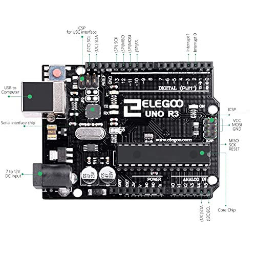
For the UNO pins in these examples, see the Arduino UNO R3 pinout guide.

FAQ

What value resistor do I need for a pull-up?

10 kOhm is the standard value for a button. Use 4.7 kOhm for a stronger pull on a long wire or a noisy environment, and for I2C buses. The range of 4.7 kOhm to 10 kOhm covers most button and sensor work.

Can I use INPUT_PULLUP instead of a resistor?

Yes, for a button on a short wire. The internal pull-up on an Arduino is 20 kOhm to 50 kOhm, which is strong enough for a bench test. Use an external 10 kOhm resistor for a long wire, a noisy environment, or a pin with no internal pull-up, such as GPIO 34 to 39 on the ESP32.

Why does my button read pressed when nobody touches it?

The pin is floating. Nothing drives it when the button is open, so noise flips the reading. Add a pull-up resistor, or enable INPUT_PULLUP, and the pin reads a stable high when released.

Should I use a pull-up or a pull-down?

Use a pull-up when your microcontroller has a built in pull-up, which most do, and when a button to ground is the simplest wiring. Use a pull-down when you need pressed to read high, or when the sensor output is open drain to ground.

Do I need a pull-up on every input pin?

Every input pin that can float needs a default level, either from a pull-up, a pull-down, or a device that always drives it. A pin connected to a sensor output that always drives the line does not need one. A pin connected to a button or a switch always does.

Parts used

ELEGOO UNO R3 Microcontroller Board: the Arduino board used in the button examples. ELEGOO Dupont Jumper Wire Set, 120-Piece: the jumper wires for the breadboard button wiring.

Sources

Last updated: 2026-11-21. Search volume: not verified. Product links use the store short link form with the product ID; confirm the product slug at publish time.
ADC Explained: Resolution, Reference Voltage, and ESP32 Limits

Push button wired to an Arduino input pin with a 10k pull-up resistor

ADC Explained: Resolution, Reference Voltage, and ESP32 Limits

An ADC, or analog to digital converter, turns a voltage into a number. A 12-bit ADC divides its input range into 4,096 steps, numbered 0 to 4,095. A 10-bit ADC divides the range into 1,024 steps, numbered 0 to 1,023. The reference voltage sets the top of that range, and on the ESP32 ADC2 pins stop working while Wi-Fi runs.

ADC explained: what is an ADC?

An ADC measures a voltage on a pin and returns a digital number. The number is proportional to the input voltage divided by the reference voltage, times the number of steps. A sensor that outputs a voltage, such as a temperature sensor, a light sensor or a potentiometer, needs an ADC to turn its signal into a number your code can use. A sensor that outputs a digital signal, such as an I2C temperature sensor, does not need an ADC, because the sensor chip does the conversion itself.

Most microcontroller ADCs use successive approximation, or SAR. The ADC samples the pin voltage, compares it against an internal reference in a series of steps, and writes a digital value. The conversion takes microseconds, and the result is a single number per read. That number is not a voltage until your code converts it, using the resolution and the reference voltage.

What is resolution and why does it matter?

Resolution is the number of bits in the ADC result, and it decides the smallest voltage change the ADC can see. A 10-bit ADC has 1,024 steps. A 12-bit ADC has 4,096 steps. On a 3.3 V range, a 10-bit step is 3.3 V divided by 1,024, or about 3.22 mV per step. A 12-bit step is 3.3 V divided by 4,096, or about 0.81 mV per step. The 12-bit ADC sees a change four times smaller than the 10-bit ADC.

ADC resolution (bits) Steps (count) Step size on 3.3 V (mV) Boards
10 1,024 3.22 Arduino Uno, Nano, ESP8266
12 4,096 0.81 ESP32, ESP32-S3, Raspberry Pi Pico, RP2040

More bits do not always mean more accuracy. The ESP32 ADC is 12-bit, but its effective resolution is about 10 to 11 bits, because noise and nonlinearity eat the last bits. Averaging 16 to 64 readings gives a steadier result than chasing the last bit of a single read. A 10-bit ADC on an Arduino Uno with a clean supply and a short wire can beat a noisy 12-bit reading on a long wire next to a Wi-Fi antenna.

What is reference voltage?

The reference voltage is the voltage that maps to the top ADC value. On an Arduino Uno, the default reference is the 5 V supply, so a 5 V input reads 1,023 and a 2.5 V input reads about 511. On the Raspberry Pi Pico, the reference is 3.3 V, so a 3.3 V input reads 4,095. On the ESP32, the reference voltage is about 1.1 V at the ADC itself, not 3.3 V, and the chip applies attenuation to scale the input before it reaches the ADC.

That ESP32 detail causes the most confusion. A 3.3 V signal on an ESP32 ADC pin does not damage the pin, because the attenuation scales it down before the converter, but the raw reading does not map linearly to 3.3 V without the attenuation setting. Use analogReadMilliVolts on the ESP32 Arduino core, which applies the factory calibration and returns millivolts, instead of converting the raw count yourself with a 3.3 V assumption.

What is attenuation on the ESP32?

Attenuation reduces the input voltage before it reaches the ADC, which widens the measurable range. The ESP32 Arduino core offers four settings: 0 dB, 2.5 dB, 6 dB and 11 dB. At 0 dB, the measurable range is about 0 mV to 950 mV. At 2.5 dB, it is about 100 mV to 1,250 mV. At 6 dB, it is about 150 mV to 1,750 mV. At 11 dB, it is about 150 mV to 2,450 mV, which is the widest range and the default in the Arduino core.

Set the attenuation per pin for your sensor range. A sensor that outputs 0 V to 1 V needs 2.5 dB attenuation. A sensor that outputs 0 V to 3.3 V needs 11 dB attenuation, and even then the top of the range saturates at about 3.1 V. The ESP32 ADC is also nonlinear near the ends of its range, so readings near 0 mV and near the top are compressed. For a battery voltage measurement, use a voltage divider that keeps the ADC input in the middle of its range, and average many readings.

Why does ADC2 stop working with Wi-Fi on the ESP32?

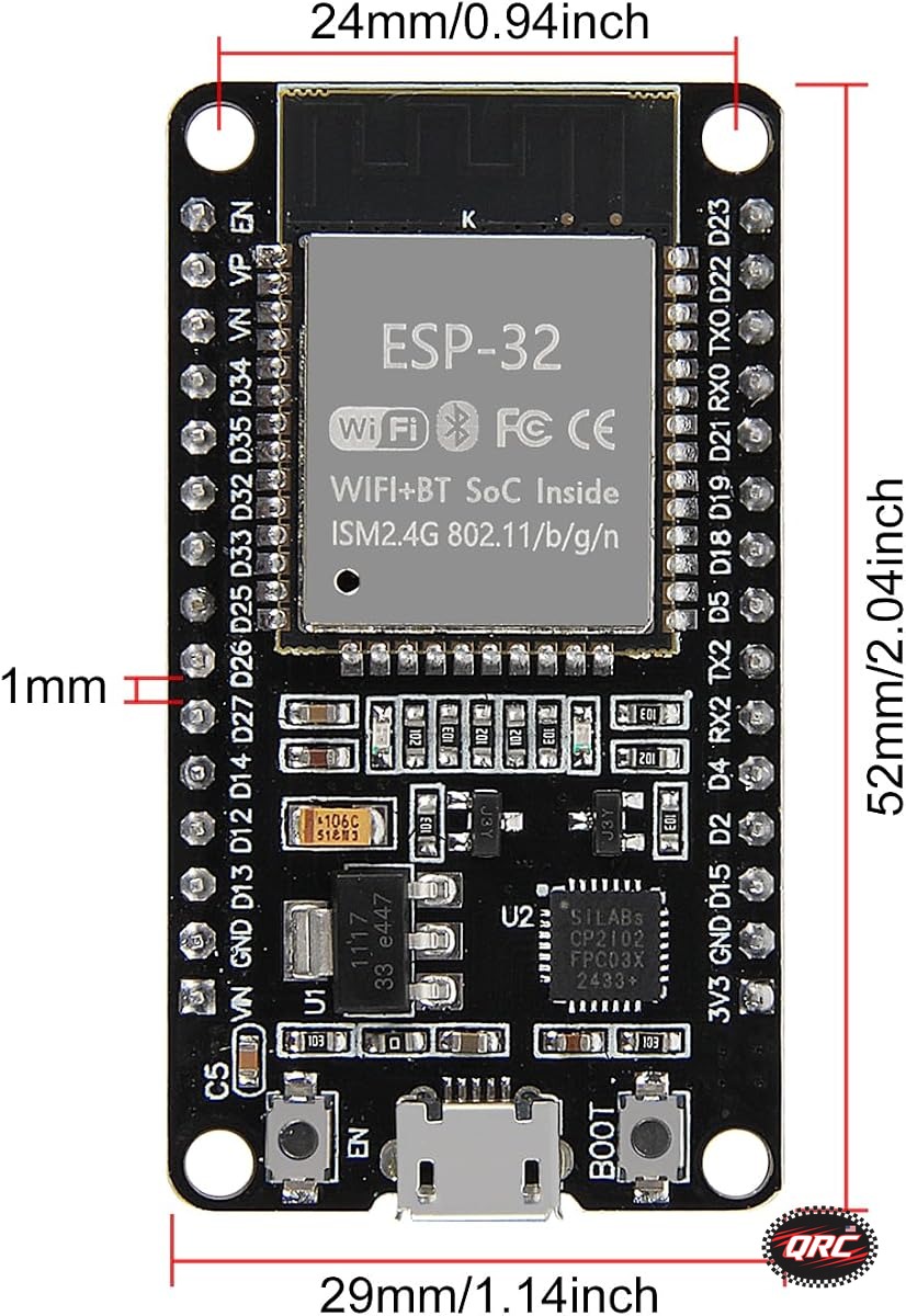
The original ESP32 has two ADC units. ADC1 has 8 channels on GPIO 32 to 39. ADC2 has 10 channels on GPIO 0, 2, 4, 12 to 15 and 25 to 27. The Wi-Fi driver uses ADC2 internally, so ADC2 cannot be read while Wi-Fi is active. The Espressif ESP-IDF ADC guide states this directly: the application can only use ADC2 when the Wi-Fi driver has not started, and a read on ADC2 fails between Wi-Fi start and Wi-Fi stop.

The symptom is a sensor that reads correctly before WiFi.begin and returns zero or a stale value after the connection starts. The fix is to move the sensor to an ADC1 pin, GPIO 32 to 39. Remember that GPIO 34 to 39 are input only, so they read a sensor but cannot drive an output. The S3 also restricts ADC2 while Wi-Fi runs. The C3 has only one ADC unit, so it has no ADC2 conflict at all. Check the ADC section of your chip datasheet before you wire a sensor.

Some ADC2 pins carry extra traps. GPIO 0, 2 and 15 are strapping pins, so a sensor on those pins can stop the board from booting. On the ESP32 DevKitC, GPIO 0 cannot be used freely because of the auto program circuit. Prefer ADC1 pins for any sensor in a Wi-Fi project, and keep ADC2 for projects with no Wi-Fi at all.

How do Arduino, ESP32 and Pico ADCs compare?

Spec (unit) Arduino Uno ATmega328P ESP32 Raspberry Pi Pico RP2040
Resolution (bits) 10 12 12
Steps (count) 1,024 4,096 4,096
ADC channels (count) 6 on DIP, 8 on TQFP 18 across two units 4 external plus temperature
Reference voltage (V) 5, supply by default About 1.1 before attenuation 3.3
Max sample rate About 10 ksps Up to 2 Msps with DMA 500 ksps
Wi-Fi conflict None ADC2 blocked by Wi-Fi None on base Pico

The Pico ADC is the simplest to use: a 3.3 V reference, 12-bit resolution, and no Wi-Fi conflict on the base board. The Arduino ADC is the simplest to understand: a 5 V reference and a direct count to voltage conversion. The ESP32 ADC is the most capable and the most confusing, because of its attenuation settings and its ADC2 conflict, so read the ADC section of the ESP-IDF guide before you trust a reading.

How do you get an accurate reading?

Follow five steps. First, pick an ADC1 pin on the ESP32, or any ADC pin on the Pico or Arduino. Second, set the attenuation for your sensor range on the ESP32, or set the reference on the Arduino. Third, keep the wires short and add a 0.1 uF capacitor from the ADC pin to ground to filter noise. Fourth, average 16 to 64 readings instead of trusting one. Fifth, use the calibrated millivolt function where the core provides one, such as analogReadMilliVolts on the ESP32, instead of converting the raw count with an assumed reference.

Never exceed the ADC input voltage. On the ESP32, the pin tolerates 3.3 V, but the measurable range tops out near 3.1 V at 11 dB attenuation. On the Pico, the pin tolerates 3.3 V and the ADC input must stay below the 3.3 V supply plus a small margin. On the Arduino Uno, the pin tolerates 5 V. A sensor that outputs more than the ADC range needs a voltage divider, and the divider ratio must be included in your conversion math.

Code: read an ESP32 ADC pin with averaging

The sketch below reads an ESP32 ADC1 pin with 11 dB attenuation and averages 32 readings. It uses the ESP32 Arduino core. It was not compiled in this draft, and the compile result is logged as code not compiled in the header.

// ESP32 ADC read with averaging on an ADC1 pin
// Board: ESP32 DevKit V1. Sensor on GPIO 34, which is ADC1 channel 6.
const int adcPin = 34; // ADC1 only, so Wi-Fi can run at the same time

void setup() {
  Serial.begin(115200);
  analogSetPinAttenuation(adcPin, ADC_11db); // Widest range, about 0 to 3.1 V
  analogReadResolution(12); // 12-bit result, 0 to 4095
}

void loop() {
  long total = 0;
  for (int i = 0; i < 32; i++) {
    total += analogReadMilliVolts(adcPin); // Calibrated millivolts, not raw counts
    delay(2);
  }
  long averageMilliVolts = total / 32;
  Serial.print("Sensor voltage (mV): ");
  Serial.println(averageMilliVolts);
  delay(500);
}

For the Pico ADC pins in this guide, see the Raspberry Pi Pico pinout guide.

FAQ

Why does my ESP32 analogRead return 0 when Wi-Fi is on?

Your sensor is on an ADC2 pin, and the Wi-Fi driver uses ADC2. Move the sensor to an ADC1 pin, GPIO 32 to 39, and the readings return.

Is a 12-bit ADC always better than a 10-bit ADC?

No. A 12-bit ADC has finer steps, but noise and nonlinearity limit its effective resolution to about 10 to 11 bits on the ESP32. A clean 10-bit reading beats a noisy 12-bit reading, so average many samples and keep wires short.

What voltage can I put on an ESP32 ADC pin?

Up to 3.3 V on the pin. The measurable range tops out near 3.1 V at 11 dB attenuation, so a sensor above that needs a voltage divider.

How many ADC pins does the ESP32 have?

18 channels across two ADC units: 8 on ADC1 at GPIO 32 to 39, and 10 on ADC2 at GPIO 0, 2, 4, 12 to 15 and 25 to 27. A 30-pin board exposes 16 of them, because GPIO 37 and 38 are not broken out.

What is the ADC reference voltage on an Arduino Uno?

5 V by default, from the supply. A 5 V input reads 1,023 and a 2.5 V input reads about 511. The reference can be changed to the internal 1.1 V bandgap or an external AREF voltage.

Parts used

ESP32 DevKit V1 Development Board, 30-Pin WROOM-32: the ESP32 board for the ADC examples, with 18 ADC channels. ELEGOO UNO R3 Microcontroller Board: the Arduino board for the 10-bit ADC comparison.

Sources

Last updated: 2026-11-21. Search volume: not verified. Product links use the store short link form with the product ID; confirm the product slug at publish time.

How to Read a Microcontroller Datasheet: Specs That Matter

Microcontroller datasheet open beside an ESP32 board and a Raspberry Pi Pico

How to Read a Microcontroller Datasheet: Specs That Matter

Read a microcontroller datasheet in this order: absolute maximum ratings first, recommended operating conditions second, the pinout and pin function table third, and the electrical characteristics fourth. The single most important distinction is that absolute maximum ratings are stress limits that damage the chip when exceeded, while recommended operating conditions are the values the chip is guaranteed to work at.

Microcontroller datasheet: what is a datasheet and which document do you need?

A datasheet is the manufacturer document that defines a chip: its features, its pinout, its electrical limits, its timing and its package. It is the primary source for every spec in a project, and it outranks tutorials, forum posts and product listings. When two sources disagree, the datasheet wins.

Three documents are often confused. The chip datasheet covers the silicon, such as the ESP32 or the RP2040. The module datasheet covers the module built on that chip, such as the ESP32-WROOM-32, including its antenna and its flash. The board schematic and board guide cover the development board, such as the ESP32 DevKit V1 or the Raspberry Pi Pico, including which chip pins reach the header and which are used by the USB chip or the flash. Chip pins and board pins differ, so read the board document for wiring and the chip datasheet for limits.

Check the revision and the date on the first page. The Espressif ESP32 Series Datasheet is at version 5.3 in the copy checked for this post. The ESP32-C3 Series Datasheet is at version 2.5. The Raspberry Pi RP2040 Datasheet is at build date 2025-02-20, build version 3184e62-clean. The Microchip ATmega328P datasheet is DS40002061B. A revision changes pin functions, current limits and errata, so a tutorial written against an old revision can be wrong for the chip you hold.

What are absolute maximum ratings?

Absolute maximum ratings are the stress limits beyond which the chip can be damaged. They are not operating conditions, and the chip is not guaranteed to work at them. The ATmega328P datasheet, DS40002061B, lists the absolute maximum supply voltage as 6.0 V, the voltage on any pin except RESET as minus 0.5 V to VCC plus 0.5 V, the DC current per I/O pin as 40 mA, and the DC current through the VCC and GND pins as 200 mA. Those numbers describe the point of damage, not a design target.

The recommended operating conditions for the same chip are stricter: the supply voltage is 1.8 V to 5.5 V, and the output voltages are guaranteed only up to 20 mA per pin. Design to 5.5 V and 20 mA, not to 6.0 V and 40 mA. A pin that survives 40 mA for a minute can still degrade, and a design that relies on an absolute maximum rating is a design that fails in the field.

The ESP32 datasheet follows the same pattern. Its GPIO pins are 3.3 V logic and are not 5 V tolerant, so a 5 V signal on an ESP32 GPIO pin exceeds the absolute maximum input voltage and can damage the pin. The RP2040 datasheet lists its I/O voltage range as 1.8 V to 3.3 V, with the same rule: a 5 V signal on a 3.3 V pin is out of spec. Read the absolute maximum input voltage row before you connect any signal, and use a level shifter when the voltages differ.

How do you read the pinout and pin function tables?

Start with the pinout diagram, which shows the physical package and the pin numbers. Then read the pin function table, which lists every pin, its name, its type and its alternate functions. A single GPIO pin on an ESP32 can serve as a digital input, a PWM output, an ADC input, an I2C line, a UART line or a touch input, depending on the configuration. The table tells you which functions each pin supports, and which pins support none of them.

Watch for four traps in the pin table. First, input only pins: GPIO 34 to 39 on the original ESP32 can read a signal but cannot drive one, and they have no internal pull-up or pull-down resistors. Second, strapping pins: GPIO 0, 2 and 15 on the ESP32, and GPIO 0, 2 and 15 on the ESP8266, must sit at specific levels at boot, so a sensor on those pins can stop the board from starting. Third, pins shared with flash memory: on many ESP32 boards, GPIO 6 to 11 connect to the flash chip and are not usable. Fourth, ADC pins shared with Wi-Fi: ADC2 pins on the ESP32 cannot be read while Wi-Fi runs.

On the RP2040, the pin function table shows that all 30 GPIO pins support PIO, and that GPIO 26 to 29 double as the four ADC inputs. On the ATmega328P, the table shows 23 programmable I/O lines, with 6 ADC inputs on the DIP package and 8 on the TQFP package, because ADC6 and ADC7 exist only on the surface mount package. That package difference is the kind of detail that only the datasheet gives you.

What do the electrical characteristics tell you?

The electrical characteristics section lists the numbers your circuit design depends on: input high and low voltage thresholds, output high and low voltages at a given current, input leakage current, pull-up resistor values and supply current in each sleep mode. Two rows matter most for a beginner build: the input high threshold, called VIH, and the input low threshold, called VIL.

On the ATmega328P at 5 V, the datasheet treats anything above 3.0 V, or 60 percent of VCC, as a definite high, and anything below 1.5 V, or 30 percent of VCC, as a definite low. The region between 1.5 V and 3.0 V is undefined, and a floating pin wanders through it. That is why a floating input reads randomly, and why a pull-up or pull-down resistor is needed. The ESP32 and RP2040 have their own VIH and VIL rows, and they differ, so check the row for your chip before you assume a 3.3 V signal is high enough for a 5 V input.

Current limits live in the same section. The ATmega328P guarantees its output voltages only up to 20 mA per pin, with a 200 mA total through the VCC and GND pins, and a 100 mA limit per pin group for sinking current. The ESP32 datasheet lists a recommended maximum of about 12 mA per GPIO pin for a reliable output level, with higher currents allowed only as absolute maximums. The RP2040 datasheet lists a 12 mA drive strength setting per pin. Never drive a motor, a relay or a solenoid directly from a GPIO pin on any of these chips: use a transistor or a driver board.

How do you use the ADC, PWM and peripheral sections?

Each peripheral has its own section with its own limits. The ADC section gives the resolution, the channel count, the reference voltage and the input range. The ESP32 has two 12-bit SAR ADCs with 18 channels, and its reference voltage is about 1.1 V before attenuation. The RP2040 has a 12-bit ADC with 4 external channels plus a temperature sensor, running at up to 500 ksps. The ATmega328P has a 10-bit ADC with 6 or 8 channels, depending on the package.

The PWM section gives the channel count and the resolution. The ESP32 has 16 LEDC channels. The RP2040 has 16 PWM channels in 8 slices. The ATmega328P has 6 PWM channels from its three timers. The UART, SPI and I2C sections give the maximum clock rates and the pin assignments, which decide whether a display or a sensor can run at the speed your project needs.

What is the errata and why should you read it?

The errata, or chip revision document, lists the known bugs in a specific chip revision and the workarounds. The ESP32 has a chip revision guide that documents differences between revision 0, 1 and 3 silicon. A bug that affects your project may already be documented there with a workaround, and a tutorial written before the errata may describe behaviour that no longer applies.

Check the chip revision of your board against the errata before you blame your code. The revision is printed on the chip or reported by the development tools. A project that works on one revision and fails on another is usually an errata issue, not a wiring fault.

Worked example: check a sensor pin before you wire it

Follow these steps for any new sensor. First, open the chip datasheet for your board and find the pin function table. Confirm the pin you plan to use supports the function you need, such as ADC input or I2C. Second, check the absolute maximum ratings for the input voltage on that pin, and confirm your sensor output stays inside it. Third, check whether the pin is a strapping pin, an input only pin or an ADC2 pin that conflicts with Wi-Fi. Fourth, check the board schematic to confirm the pin reaches the header and is not used by the USB chip or the flash. Fifth, wire it and test it on the bench before you solder it.

For one datasheet section in depth, see the ADC explained guide.

FAQ

What is the difference between absolute maximum and recommended ratings?

Absolute maximum ratings are stress limits that damage the chip when exceeded. Recommended operating conditions are the values the chip is guaranteed to work at. Design to the recommended values, never to the absolute maximums.

How much current can a GPIO pin supply?

On the ATmega328P, outputs are guaranteed only up to 20 mA per pin, with 40 mA as the absolute maximum. On the ESP32 and RP2040, plan for about 12 mA per pin. Never drive a motor or relay directly from a GPIO pin.

Where do I find the pinout for my exact board?

Read the board schematic or board guide for your exact board variant, not the chip datasheet alone. Chip pins and board pins differ, because the board uses some chip pins for flash, USB and the power circuit.

Why does the datasheet revision matter?

A revision changes pin functions, current limits and errata. A tutorial written against an old revision can be wrong for the chip you hold, so check the revision on the first page of the datasheet you read.

What is a strapping pin?

A strapping pin is a pin whose level at boot selects a boot mode, such as flash boot or download mode. A sensor on a strapping pin can stop the board from starting, so check the strapping table before you wire a sensor to GPIO 0, 2 or 15 on an ESP32.

Parts used

ESP32 DevKit V1 Development Board, 30-Pin WROOM-32: the ESP32 board used in the worked examples. Raspberry Pi Pico Development Board, 2-Pack: the RP2040 board used in the worked examples.

Sources

Last updated: 2026-11-21. Search volume: not verified. Product links use the store short link form with the product ID; confirm the product slug at publish time.

Raspberry Pi Pico Pinout: RP2040 GPIO, ADC, and Power

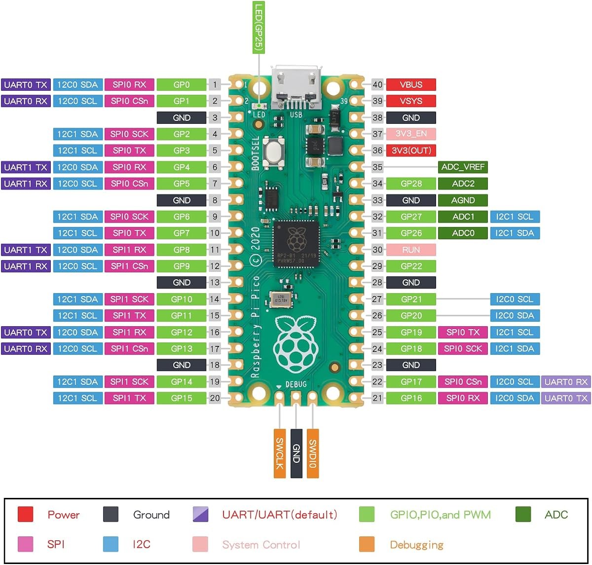
Raspberry Pi Pico board with 40-pin edge and USB port. Caption: Raspberry Pi Pico board with 40-pin edge. Description: Top view of the Raspberry Pi Pico board used in this pinout guide.

Raspberry Pi Pico Pinout: RP2040 GPIO, ADC, and Power

Answer in brief: The Raspberry Pi Pico has 26 GPIO pins, 3 ADC inputs, and PWM on every GPIO pin. It runs the RP2040 chip at a 133 megahertz clock and 3.3 volt logic. This guide maps each pin, the power pins, and the debug pins. It also covers the pins that are not general GPIO.

Quick Facts

Item Detail Source
Chip RP2040, dual-core Cortex-M0+ Raspberry Pi Pico Datasheet
Clock speed 133 megahertz Raspberry Pi Pico Datasheet
Logic voltage 3.3 volts, not 5 volt tolerant Raspberry Pi Pico Datasheet
Board edge 40 pins Raspberry Pi Pico Datasheet
GPIO pins 26 pins: GP0 to GP22 and GP26 to GP28 Raspberry Pi Pico Datasheet
ADC inputs 3 inputs: GP26, GP27, GP28, 12-bit RP2040 Datasheet
ADC range 0 counts to 4095 counts, 0 volts to 3.3 volts RP2040 Datasheet
Onboard LED GP25 Raspberry Pi Pico Datasheet
VSYS input range 1.8 volts to 5.5 volts Raspberry Pi Pico Datasheet
VBUS pin Pin 40, USB 5 volt input Raspberry Pi Pico Datasheet
3V3 output, max 300 milliamperes Raspberry Pi Pico Datasheet
PWM Every GPIO pin, 8 slices RP2040 Datasheet

Raspberry Pi Pico Pinout Table

This table is an original pinout table built from the Raspberry Pi Pico Datasheet. It is not a copied image. The GP names are the printed pin names on the board. The pin numbers are the board edge numbers.

Edge pin GP name Main function Notes
1 GP0 GPIO UART0 TX default
2 GP1 GPIO UART0 RX default
3 GND Ground Common ground
4 GP2 GPIO I2C1 SDA option
5 GP3 GPIO I2C1 SCL option
6 GP4 GPIO UART1 TX, I2C0 SDA default
7 GP5 GPIO UART1 RX, I2C0 SCL default
8 GND Ground Common ground
9 GP6 GPIO I2C1 SDA default
10 GP7 GPIO I2C1 SCL default
11 GP8 GPIO SPI1 RX default
12 GP9 GPIO SPI1 CSn default
13 GND Ground Common ground
14 GP10 GPIO SPI1 SCK default
15 GP11 GPIO SPI1 TX default
16 GP12 GPIO General use
17 GP13 GPIO General use
18 GND Ground Common ground
19 GP14 GPIO General use
20 GP15 GPIO General use
21 GP16 GPIO SPI0 RX default
22 GP17 GPIO SPI0 CSn default
23 GND Ground Common ground
24 GP18 GPIO SPI0 SCK default
25 GP19 GPIO SPI0 TX default
26 GP20 GPIO General use
27 GP21 GPIO General use
28 GND Ground Common ground
29 GP22 GPIO General use
30 RUN Reset Active low, pull low to reset
31 GP26 ADC0 Analog input, 12-bit
32 GP27 ADC1 Analog input, 12-bit
33 AGND Analog ground Ground for ADC use
34 GP28 ADC2 Analog input, 12-bit
35 ADC_VREF ADC reference 3.3 volt reference input
36 3V3(OUT) 3.3 volt output 300 milliamperes max
37 3V3_EN 3.3 volt enable Pull low to disable the regulator
38 GND Ground Common ground
39 VSYS Power input 1.8 volts to 5.5 volts input
40 VBUS Power input USB 5 volt input

Power Pins

Power the Pico through USB, the VBUS pin, or the VSYS pin. USB gives 5 volts to VBUS. VBUS is pin 40 on the board edge. VSYS is pin 39 on the board edge. VSYS accepts 1.8 volts to 5.5 volts. That range covers a battery pack and a 5 volt supply.

Use VSYS for battery power. A 3-cell pack or a single lithium cell with a boost stage can feed VSYS. Check the Pico Datasheet power section before you pick a battery. A battery above 5.5 volts can damage the board. A battery below 1.8 volts will not run the regulator.

The 3V3(OUT) pin is pin 36. It gives 3.3 volts at a max of 300 milliamperes. That value comes from the Raspberry Pi Pico Datasheet. Use it for sensors and small loads. A part that needs more current needs its own regulator.

Pin 37 is 3V3_EN. It enables the 3.3 volt regulator. Leave it alone for normal use. Pull it low only when you want to shut the regulator down. Pin 35 is ADC_VREF. It sets the ADC reference. Leave it at 3.3 volts for normal use.

Boot and Reset Pins

The Pico has a BOOTSEL button for firmware loading. Hold BOOTSEL while you plug in USB. The board then appears as a USB drive. Drag a UF2 file onto that drive to load new firmware. Release BOOTSEL after the drive appears. That path loads MicroPython, CircuitPython, or a C build.

Pin 30 is RUN. It resets the chip when pulled low. It is active low. Connect a button from RUN to ground for a manual reset. Release the button to let the chip run again. Do not hold RUN low for normal use.

ADC Pins

The Pico has 3 ADC inputs on the board edge: GP26, GP27, and GP28. They are ADC0, ADC1, and ADC2. Each input reads 12-bit values from 0 counts to 4095 counts. A 0 volt input reads 0 counts. A 3.3 volt input reads 4095 counts. That step size is about 0.8 millivolts per count at the default reference.

ADC3 is an internal channel. It reads VSYS through GP29. It does not appear on the board edge. Use ADC3 in code to check the supply voltage. That read helps a battery project track its own power.

PWM Pins

PWM works on every GPIO pin on the Pico. The RP2040 chip has 8 PWM slices. Each slice drives 2 pins. That gives 16 PWM channels across the 26 GPIO pins. The Pico Datasheet and the RP2040 Datasheet both list this layout.

PWM drives a signal, not a load. Use a transistor or a driver for a motor. Use a series resistor for an LED. RP2040 GPIO pins have four drive-strength settings, nominally 2, 4, 8, and 12 mA, per the RP2040 Datasheet, section 5.5.3.5. The highest setting is 12 mA per pin. The total current sourced by all GPIO and QSPI pins together must not exceed 50 mA, and the total sunk must not exceed 50 mA, per the same datasheet (IIOVDD_MAX and IIOVSS_MAX). Those are drive-strength modes, not hard per-pin limits, and the pin voltage sags as the load rises. Keep LED current low with a resistor.

I2C Pins

I2C0 uses GP4 for SDA and GP5 for SCL by default. I2C1 uses GP6 for SDA and GP7 for SCL by default. Those defaults are the common pin choices in Pico examples. The RP2040 chip can route I2C to many other pins. Check the RP2040 Datasheet pin function table before you move the bus.

I2C runs at 3.3 volt logic on this board. Check the device voltage before you connect it. A 5 volt I2C device needs a level shifter. A direct 5 volt connection can damage the Pico.

SPI Pins

SPI0 uses GP16 for RX, GP17 for CSn, GP18 for SCK, and GP19 for TX by default. SPI1 uses GP8 for RX, GP9 for CSn, GP10 for SCK, and GP11 for TX by default. Those defaults are the common pin choices in Pico examples. The RP2040 chip can route SPI to many other pins.

SPI runs at 3.3 volt logic on this board. Check the device voltage before you connect it. A 3.3 volt SPI device connects directly. A 5 volt SPI device needs a level shifter.

UART Pins

UART0 uses GP0 for TX and GP1 for RX by default. UART1 uses GP4 for TX and GP5 for RX by default. Those defaults are the common pin choices in Pico examples. The RP2040 chip can route UART to many other pins. Check the RP2040 Datasheet pin function table before you move the port.

The USB port carries a separate serial link for MicroPython and for debug output. That link does not use GP0 or GP1. You can use GP0 and GP1 for a device while the USB console stays open. That split is handy for GPS logging.

USB and SWD Debug Pins

For a Pico comparison, see the live post Raspberry Pi Pico vs Pico W vs Pico 2: Chip, Wireless, and Headers (live post #20577). For starter kit options, see the live post Raspberry Pi Pico Starter Kits Compared: SunFounder, LAFVIN, and More (live post #20579).

Pins to Avoid

Avoid GP23, GP24, GP25, and GP29 as general GPIO. They are internal pins. GP25 is the onboard LED on the Pico. Use it only for the LED. GP24 senses VBUS. GP29 monitors VSYS. GP23 controls power save.

On the Pico WH, GP23, GP24, GP25, and GP29 are used by the onboard wireless chip instead, per the Raspberry Pi Pico W Datasheet. The onboard LED on the Pico WH is driven by the wireless chip, not by GP25, so the GP25 LED blink in the sketch below works on the Pico only, not on the Pico WH. In MicroPython, use Pin(“LED”, Pin.OUT) on the Pico WH.

Avoid 5 volt logic on any GPIO pin. This board uses 3.3 volt logic only. It is not 5 volt tolerant. A 5 volt signal needs a level shifter. A direct 5 volt input can damage the pin.

Max Current and Logic Voltage

Logic voltage is 3.3 volts on every GPIO pin. That value comes from the Raspberry Pi Pico Datasheet. Treat 3.3 volts as the high level. Treat 0 volts as the low level. The board is not 5 volt tolerant. That warning is in the datasheet.

The 3V3(OUT) pin gives 3.3 volts at a max of 300 milliamperes. That value comes from the Raspberry Pi Pico Datasheet. Treat 300 milliamperes as the working limit for that pin. A larger load needs its own regulator.

The RP2040 GPIO pins have four drive-strength settings, nominally 2, 4, 8, and 12 mA, per the RP2040 Datasheet, section 5.5.3.5. The highest setting is 12 mA per pin. The total current sourced by all GPIO and QSPI pins together must not exceed 50 mA, and the total sunk must not exceed 50 mA (IIOVDD_MAX and IIOVSS_MAX). Treat 12 mA per pin and 50 mA total as the working limits.

Use a driver for any load above a small LED. Keep LED current low with a series resistor. A 220 ohm resistor is a common bench value for a 3.3 volt LED test. Check the LED datasheet for its own forward voltage before you pick a resistor.

Wiring and Power Warnings

Power the board before you connect a sensor. Keep the USB cable short. Use a cable under 3 feet for bench tests when you can. Long wires pick up noise. Noise causes ADC jitter and I2C errors.

Do not feed 5 volts into a GPIO pin. Do not feed 5 volts into the 3V3(OUT) pin. Do not feed more than 5.5 volts into VSYS. Each of those mistakes can damage the board. Check the pin labels before every connection.

Pin Test Sketch

Language: MicroPython. Firmware: MicroPython version 1.22.2 for RP2040. No extra library install is needed for this test. Load the firmware with the BOOTSEL drive method. Code status: code not compiled. No arduino-cli or PlatformIO is installed in this environment.

# Raspberry Pi Pico pin test script
# Language: MicroPython version 1.22.2 for RP2040
# Board: Raspberry Pi Pico, RP2040
# Code status: code not compiled

from machine import Pin, ADC, PWM
import time

# Onboard LED is GP25 on the Pico. On the Pico WH the LED is on the wireless chip, not GP25.
led = Pin(25, Pin.OUT)

# ADC test uses GP26, which is ADC0.
adc = ADC(Pin(26))

# PWM test uses GP15 at 1000 hertz.
pwm = PWM(Pin(15))
pwm.freq(1000)  # Set PWM frequency to 1000 hertz.
pwm.duty_u16(0)  # Start with the output off.

# UART test uses UART0 on GP0 TX and GP1 RX.
# The USB console stays free for print output.
from machine import UART
uart = UART(0, baudrate=9600, tx=Pin(0), rx=Pin(1))

print("Pico pin test started")

while True:
    # Read the ADC value on GP26.
    # ADC range is 0 to 65535 counts in MicroPython.
    value = adc.read_u16()
    print("GP26 ADC value:", value)

    # Convert the ADC value to a voltage from 0 to 3.3 volts.
    volts = value * 3.3 / 65535
    print("GP26 volts:", volts)

    # Fade the PWM output on GP15 from off to full.
    for level in range(0, 65536, 4096):
        pwm.duty_u16(level)
        time.sleep(0.05)  # Wait 50 milliseconds per step.

    # Blink the onboard LED on GP25 once per loop.
    led.on()
    time.sleep(0.5)  # Wait 500 milliseconds.
    led.off()
    time.sleep(0.5)  # Wait 500 milliseconds.

Expected result: the console shows a GP26 ADC value and a voltage each loop. The value changes with the voltage on GP26. The PWM output on GP15 fades up in steps. The onboard LED blinks once per loop. If no console output appears, check the MicroPython firmware load and the serial port selection.

Frequently Asked Questions

How many GPIO pins does the Pico have?

It has 26 GPIO pins: GP0 through GP22, plus GP26, GP27, and GP28. GP23, GP24, GP25, and GP29 are internal pins. They do not appear on the board edge as general GPIO.

Which pins are ADC on the Pico?

GP26 is ADC0, GP27 is ADC1, and GP28 is ADC2. Each input reads 12-bit values from 0 counts to 4095 counts. ADC3 is an internal channel that reads VSYS.

Is the Pico 5 volt tolerant?

No, the Pico is not 5 volt tolerant. It uses 3.3 volt logic only. A 5 volt signal needs a level shifter. A direct 5 volt input can damage the pin.

How do I load MicroPython on the Pico?

Hold BOOTSEL while you plug in USB. The board appears as a USB drive. Drag the MicroPython UF2 file onto that drive. The board reboots with MicroPython running.

Boards That Match This Pinout

These boards use the pinout in this guide. Check the product page for current stock before you order. Stock changes over time.

Related reading: compare this board with ESP32 boards in the staged pillar RP2040 vs ESP32 (row 24, staged). For sibling pinouts, see Arduino UNO R3 Pinout and Nano V3.0 USB-C Guide: ATmega328P Board for Arduino IDE.

Sources

  • Raspberry Pi Pico Datasheet, https://datasheets.raspberrypi.com/pico/pico-datasheet.pdf
  • RP2040 Datasheet, https://datasheets.raspberrypi.com/rp2040/rp2040-datasheet.pdf
  • Raspberry Pi Pico W Datasheet, https://pip.raspberrypi.com/documents/RP-008312-DS-pico-w-datasheet.pdf
  • Raspberry Pi Pico pinout guide, https://www.raspberrypi.com/documentation/microcontrollers/raspberry-pi-pico.html

Last updated 2026-11-21.

RP2040 vs ESP32: PIO, Radios, and Which Board to Pick

Microcontroller datasheet open beside an ESP32 board and a Raspberry Pi Pico

RP2040 vs ESP32: PIO, Radios, and Which Board to Pick

Pick the RP2040 when your project needs precise timing, custom protocols or deterministic I/O, and pick the ESP32 when your project needs Wi-Fi or Bluetooth. The RP2040 has no wireless radio at all on the base Pico, while the ESP32 has Wi-Fi and Bluetooth built in. The RP2040 wins on PIO, and the ESP32 wins on every wireless job.

RP2040 vs ESP32 at a glance

The table below uses the Raspberry Pi RP2040 Datasheet, build date 2025-02-20, build version 3184e62-clean, and the Espressif ESP32 Series Datasheet v5.3. The Pico W adds Wi-Fi, and that variant is covered in its own section below.

Spec (unit) RP2040 (Raspberry Pi Pico) ESP32 (DevKit V1)
CPU Dual ARM Cortex-M0+ Dual Xtensa LX6
Max clock (MHz) 133 240
SRAM (KB) 264 in six banks 520
Flash (MB) 2 on Pico, external QSPI, up to 16 supported 4 in package typical, up to 16 external
GPIO pins (count) 30, 26 on Pico header plus 4 ADC shared 34
Wi-Fi None on base Pico; Pico W adds 2.4 GHz Wi-Fi Wi-Fi 4, 2.4 GHz
Bluetooth None on base Pico; Pico W adds BLE 5.2 Classic plus BLE 4.2
ADC 4 external channels plus temperature sensor, 12-bit, 500 ksps 18 channels, 12-bit, two ADC units
DAC None 2 channels, 8-bit
PWM channels (count) 16, 8 slices with 2 outputs each 16 LEDC channels
PIO state machines (count) 8, in 2 blocks of 4 None
UART (count) 2 3
SPI (count) 2 2 usable
I2C (count) 2 2
USB USB 1.1 host and device with PHY None native, USB to serial chip on board
Logic voltage (V) 3.3 3.3
Production lifetime Until at least January 2041 per datasheet 15 year longevity commitment class

One row in that table decides most projects before any other spec matters: the base RP2040 has no radio, and the ESP32 has two. If your project must connect to Wi-Fi, the base Pico is out, and the choice becomes Pico W versus ESP32, which is covered below.

What is PIO and why does it matter?

PIO stands for Programmable Input Output. The RP2040 has two PIO blocks with four state machines each, for eight state machines in total. Each state machine runs a small program written in a nine-instruction assembly language, and each PIO block holds 32 instruction slots of shared memory for its four state machines. A state machine drives GPIO pins with precise timing without using either main CPU core. That makes PIO the RP2040 feature with no equivalent on the ESP32.

PIO programs implement protocols in software that would otherwise need dedicated hardware. Common uses are WS2812 LED strips, VGA output, I2S audio, custom serial protocols and precise pulse trains. A PIO state machine can bit bang a protocol at a fixed clock rate while both Cortex-M0+ cores run your application code. The timing stays deterministic because the state machine is not interrupted by Wi-Fi, USB or a scheduler.

The ESP32 has no PIO. It has an RMT peripheral for pulse trains and an I2S peripheral for audio, and those cover many of the same jobs, but they are fixed function blocks. When a project needs a protocol that no fixed peripheral speaks, the RP2040 implements it in PIO and the ESP32 needs bit banging on a core that is also running Wi-Fi. For a robotics project that drives a custom sensor bus or a precise stepper pulse train, PIO is a real advantage.

How do the radios compare?

The base Raspberry Pi Pico has no Wi-Fi and no Bluetooth. It is a wired microcontroller. The Raspberry Pi Pico W adds a 2.4 GHz Wi-Fi radio and Bluetooth 5.2, using an Infineon CYW43439 wireless chip connected over SPI. The Pico W is the board to compare with the ESP32 when wireless matters.

The ESP32 has Wi-Fi 4 and Bluetooth Classic plus BLE 4.2 on the same chip, with an antenna on the module. Its Wi-Fi stack is mature, its Arduino and ESP-IDF support is deep, and it handles a web server, an MQTT client and Bluetooth at once on two cores at 240 MHz. The Pico W handles Wi-Fi well for sensor posting and simple web serving, but its single SPI link to the wireless chip and its 133 MHz cores give it less headroom for a heavy network load plus application code.

Choose the ESP32 when the network is the project: a web dashboard, a camera stream, a Bluetooth link or an MQTT fleet. Choose the Pico W when the project is mostly local I/O with occasional Wi-Fi, such as a sensor that posts a reading every minute. Choose the base Pico when the project has no wireless need at all.

How do CPU, memory and GPIO compare?

The ESP32 is the faster chip on paper: two Xtensa LX6 cores at 240 MHz against two Cortex-M0+ cores at 133 MHz. The ESP32 also has twice the SRAM, at 520 KB against 264 KB. For number crunching, network stacks and displays, the ESP32 is faster. For deterministic I/O, the RP2040 closes the gap, because PIO and DMA move data without the CPU, and the six independent SRAM banks let both cores and the DMA controller work in parallel without bus contention.

GPIO counts are close: 30 multifunction pins on the RP2040 against 34 on the ESP32. The RP2040 puts every GPIO on a flexible pin mux, so any peripheral can use almost any pin, and all 30 pins support PIO. The ESP32 has more fixed function pins and more ADC channels, at 18 against 4 external channels on the RP2040. If your project reads six analog sensors, the ESP32 fits and the RP2040 does not. If your project needs eight PWM outputs with precise timing, both fit, and the RP2040 PIO option is stronger.

Flash differs in form. The Pico carries 2 MB of external QSPI flash and supports up to 16 MB. The ESP32 DevKit V1 typically carries 4 MB in package. Both are ample for Arduino or MicroPython projects. The RP2040 has no on chip flash at all, so its program always lives in external flash, while the ESP32 executes from its own flash and PSRAM options.

Which is easier to program?

Both boards run MicroPython and Arduino, and both have a C SDK. The Pico is the simpler first board for MicroPython: hold BOOTSEL, plug in USB, drop the UF2 file on the drive that appears, and the board reboots into MicroPython. The ESP32 needs esptool or Thonny to flash MicroPython firmware over serial, which is one more step and one more driver.

For Arduino, the ESP32 has the larger example base, because it has been in the Arduino ecosystem longer and its Wi-Fi examples are everywhere. The Pico Arduino core is solid and growing, and it covers the same sensor and display libraries, but a search for a Pico Wi-Fi example returns fewer results than the same search for the ESP32. For C development, the Pico SDK is clean and well documented, and the ESP-IDF is more powerful and more complex.

Debugging favours the Pico. The RP2040 has a SWD debug port and the Pico exposes it on three pins, so a low cost debug probe gives breakpoints and single stepping. The ESP32 has JTAG debugging too, but on the DevKit V1 it goes through the same USB to serial path and is less direct for a beginner.

Which board should you pick for each project?

Project type Pick this board Why
Wi-Fi sensor dashboard ESP32 Native Wi-Fi, 520 KB SRAM, mature web server examples
Bluetooth link or beacon ESP32 Bluetooth Classic plus BLE on chip
WS2812 LEDs or custom protocol RP2040 PIO state machines drive timing without CPU load
Precise stepper or pulse train RP2040 PIO plus DMA gives deterministic timing
USB HID device or MIDI RP2040 Native USB 1.1 host and device with PHY
Many analog sensors ESP32 18 ADC channels against 4 on the RP2040
Low cost learning board RP2040 Simple MicroPython flash path, low price, PIO to explore
Camera or display plus Wi-Fi ESP32, or ESP32-S3 PSRAM and camera interface, see the ESP32 family post

The Pico W sits between the two columns: it is the RP2040 pick when a project needs PIO plus occasional Wi-Fi. It costs more than the base Pico and less than a full ESP32 setup in many builds, and it keeps the PIO advantage while adding a radio.

What about Pico W vs ESP32?

Pico W versus ESP32 is the fair wireless comparison. The Pico W has Wi-Fi and Bluetooth 5.2 through its CYW43439 chip. The ESP32 has Wi-Fi and Bluetooth on chip. The ESP32 wins on network headroom, on Bluetooth Classic support and on the size of its Wi-Fi example base. The Pico W wins on PIO, on native USB and on the simplicity of its MicroPython path.

For a battery sensor that wakes, reads a sensor and posts over Wi-Fi, either board works, and the Pico W often draws less power in the application because its cores run at 133 MHz. For a web server that serves a dashboard to several clients at once, the ESP32 is the safer pick. For a USB keyboard, a MIDI controller or a WS2812 project that also posts to Wi-Fi, the Pico W is the only board here that does both jobs well.

For the Pico pins behind this comparison, see the Raspberry Pi Pico pinout guide.

FAQ

Does the Raspberry Pi Pico have Wi-Fi?

No, the base Pico has no wireless radio. The Pico W adds 2.4 GHz Wi-Fi and Bluetooth 5.2. Check the board name before you buy, because the two boards look alike.

Is the RP2040 faster than the ESP32?

No, on raw CPU speed the ESP32 is faster, with two cores at 240 MHz against two cores at 133 MHz. The RP2040 is faster at deterministic I/O, because its eight PIO state machines handle timing without CPU load.

Can the Pico run Arduino code?

Yes. The Arduino Pico core supports the RP2040 in the Arduino IDE, and most sensor and display libraries work on it. Wi-Fi code for the Pico W uses different libraries from ESP32 Wi-Fi code.

Which is better for a robot car?

The ESP32 is better when the car needs Wi-Fi control or telemetry. The RP2040 is better when the car needs precise motor timing or a custom sensor protocol. A car with both needs is a Pico W or an ESP32 with a separate PIO style approach, and the deciding factor is which requirement is stricter.

What is PIO used for in practice?

PIO drives WS2812 LED strips, VGA output, I2S audio, custom serial buses and precise pulse trains. Each state machine runs a small program that drives GPIO pins at a fixed rate while the main cores run your code.

Parts used

Raspberry Pi Pico Development Board, 2-Pack: the base RP2040 board for PIO, USB and deterministic I/O projects. ESP32 DevKit V1 Development Board, 30-Pin WROOM-32: the ESP32 board for Wi-Fi, Bluetooth and networked projects.

Sources

Last updated: 2026-11-21. Search volume: not verified. Product links use the store short link form with the product ID; confirm the product slug at publish time.