
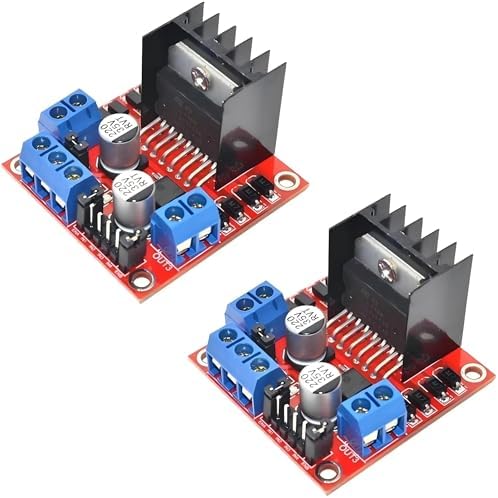
L298N vs TB6612 vs DRV8833: Which Motor Driver for Your Robot
Pick the TB6612FNG for most battery robots. It drives two DC motors from 4.5 V to 13.5 V at 1.2 A average per channel, and it loses only about 0.5 V inside the chip at 1 A. Pick the DRV8833 when your battery stays under 10.8 V, and pick the L298N only when your motor supply runs above 13.5 V.
L298N vs TB6612 vs DRV8833 at a glance
The table below uses the ST L298 datasheet DS0218 Rev 5 (October 2023), the Toshiba TB6612FNG datasheet dated 2014-10-01, which prints no revision number, and the Texas Instruments DRV8833 datasheet SLVSAR1E Rev E (July 2015). Module ratings vary with board layout and cooling, so treat the continuous current figures as planning values, not guarantees.
| Spec (unit) | L298N | TB6612FNG | DRV8833 |
|---|---|---|---|
| Switch type | Bipolar Darlington | MOSFET | MOSFET |
| Motor supply (V) | Up to 46 chip, 5 to 35 on common modules | 4.5 to 13.5, 15 absolute max | 2.7 to 10.8 |
| Continuous current per channel (A) | 2.0 | 1.2 average | 1.5 RMS, PWP and RTY packages only (0.5 RMS in PW package), with good cooling |
| Peak current per channel (A) | 3.0 non repetitive, 100 ms | 3.2 single 10 ms pulse | 2.0 |
| Voltage lost at 1 A (V) | 1.8 to 3.2 | About 0.5, from 0.5 ohm on resistance | About 0.36, from 0.36 ohm on resistance |
| Logic supply (V) | 5, module regulator or Arduino | 2.7 to 5.5 | None needed, internal |
| Standby or sleep current | 13 mA typ on VS, 24 mA typ on VSS (36 mA max on VSS) | 1 uA max in standby | 1.6 uA typ in sleep (2.5 uA max) |
| Channels (count) | 2 DC motors or 1 stepper | 2 DC motors or 1 stepper | 2 DC motors or 1 stepper |
| Built in 5 V regulator | Yes on common modules | No | No |
| Standby pin | No, enable pins only | Yes, STBY pin | Yes, sleep via nSLEEP |
Why does voltage drop decide this comparison?
A motor driver sits between the battery and the motor, and every volt it keeps is a volt the motor never sees. The L298N uses bipolar transistors, and the ST datasheet lists a total saturation drop of 1.8 V to 3.2 V at 1 A. On a 7.4 V battery with a motor drawing 1 A, the motor sees about 4.2 V to 5.6 V, and the missing 1.8 V to 3.2 V becomes heat in the driver. Heat is power lost: at 1 A and a 2 V drop, the driver burns 2 W per channel.
The MOSFET drivers lose far less. The TB6612FNG has about 0.5 ohm total on resistance, so at 1 A it drops about 0.5 V, and the heat is current squared times resistance, or 0.5 W per channel. The DRV8833 has about 0.36 ohm total on resistance, so at 1 A it drops about 0.36 V and burns about 0.36 W. On the same 7.4 V battery at 0.25 A per motor, the TB6612FNG delivers about 7.28 V and the DRV8833 about 7.31 V, while the L298N loses more than a volt at that current, so the motor sees less than the MOSFET drivers deliver. That is why a robot car runs faster and longer on a MOSFET driver with the same battery.
The practical rule is to size for stall current, not running current. A TT motor that draws 0.25 A while rolling can draw over 1 A when stalled against a wall. A driver rated for 1.2 A average per channel handles that stall briefly, but a driver run at its headline current for minutes overheats. Plan for roughly half the headline number for sustained running, and always check the stall current of your exact motor.
When should you pick the L298N?
Pick the L298N when the motor supply runs above 13.5 V. The TB6612FNG tops out at 15 V absolute maximum and the DRV8833 at 10.8 V, so a 24 V gear motor or a 12 V motor with a fully charged 4 cell LiPo that peaks above 16 V needs the L298N range. The L298N chip tolerates up to 46 V, and common modules are rated for 5 V to 35 V motor supplies.
The L298N module also suits a first build. It has screw terminals that accept thick motor wires without soldering, a heatsink, a built in 5 V regulator that can power an Arduino when the motor supply is under 12 V, and an enable jumper that every tutorial covers. Its 5 V jumper rule matters: with the jumper on and a motor supply under 12 V, the on board regulator outputs 5 V. Above 12 V, remove the jumper and power the logic separately, or the regulator overheats.
The cost of the L298N is heat and wasted battery. On a 7.4 V pack, about a quarter of the battery voltage never reaches the motor. On a 12 V supply the loss is a smaller share, so the L298N is at its best on 12 V builds and at its worst on small 2 cell battery robots.
When should you pick the TB6612FNG?
Pick the TB6612FNG for most small battery robots, including TT motor cars, N20 motor robots and 2WD chassis kits on 6 V to 12 V supplies. Its 4.5 V to 13.5 V range covers 4 AA cells, a 2 cell LiPo at 7.4 V and a 3 cell LiPo at 11.1 V. Its 1.2 A average and 3.2 A peak per channel cover TT and N20 stall currents with margin. Its STBY pin stops both motors with one logic line, which is the clean way to implement an emergency stop or a sleep mode.
The TB6612FNG logic supply runs from 2.7 V to 5.5 V, so it works directly with a 3.3 V ESP32 or a 5 V Arduino without a level shifter on the logic pins. Its low standby current, 1 uA max, suits a battery robot that sleeps between runs. Its only weakness is the 13.5 V ceiling: a 4 cell LiPo at full charge exceeds it, so a 4 cell build needs the L298N or a different driver.
When should you pick the DRV8833?
Pick the DRV8833 for compact, low voltage robots. Its 2.7 V to 10.8 V range starts at a single Li-ion cell, so a 1 cell robot at 3.7 V runs on it where the TB6612FNG needs at least 4.5 V. Its 1.5 A RMS and 2 A peak per channel in the PWP and RTY packages are the highest continuous current in this group, and its 0.36 ohm on resistance gives the lowest voltage drop and the least heat.
The DRV8833 needs no separate logic supply, because its logic runs from the motor supply internally, and it accepts 3.3 V and 5 V logic inputs. Its sleep current is 1.6 uA typ, close to the TB6612FNG standby current. Its weakness is the 10.8 V ceiling: a 3 cell LiPo at 11.1 V nominal and 12.6 V full charge exceeds it, so a 3 cell build belongs on the TB6612FNG or the L298N. It also has no built in 5 V regulator and no screw terminals on most breakout boards, so it suits a soldered build more than a first screw terminal build.
How do you wire each driver?
All three drivers use the same pattern: motor supply to VM or VS, logic supply where needed, ground shared with the microcontroller, two direction pins and one PWM enable pin per motor. On the L298N, the enable pins are ENA and ENB, and the direction pins are IN1 to IN4. On the TB6612FNG, the pins are PWMA and PWMB for speed, AIN1 and AIN2 plus BIN1 and BIN2 for direction, and STBY to enable the chip. On the DRV8833, the pins are AIN1 and AIN2 plus BIN1 and BIN2, and PWM goes on one input of each pair.
Three wiring rules apply to all three drivers. First, share the ground between the motor supply, the driver and the microcontroller, or the logic signals have no reference. Second, never power a motor from the microcontroller 5 V pin: use a separate battery or supply, and size it for the stall current. Third, add a 100 uF capacitor across the motor supply close to the driver on the TB6612FNG and DRV8833 boards, because motor current spikes pull the supply down and cause brownout resets.
Which driver for TT motors, N20 motors and 12 V builds?
| Motor or build | Pick this driver | Why |
|---|---|---|
| TT motors, 3 to 6 V, 2WD car | TB6612FNG | Low drop on a small battery, 1.2 A covers stall, STBY pin |
| N20 motors, 3 to 6 V, small robot | DRV8833 or TB6612FNG | DRV8833 for 1 cell builds, TB6612FNG for 2 cell builds |
| 12 V gear motors | L298N | Voltage headroom above 13.5 V, screw terminals, heatsink |
| 3 cell LiPo, 11.1 V car | TB6612FNG | 13.5 V ceiling covers 12.6 V full charge, low drop |
| 1 cell LiPo, 3.7 V robot | DRV8833 | Only driver here that starts at 2.7 V |
| First robot car, screw terminals | L298N | Screw terminals and 5 V regulator, simplest first wiring |
For the L298N in practice, see the L298N robot car build.
FAQ
Can the L298N run on 3.3 V logic from an ESP32?
Yes, with care. The L298N logic high threshold is about 2.3 V, so a 3.3 V ESP32 output registers as high. Power the L298N logic from 5 V where the module expects it, share the ground, and keep the motor supply separate.
Why does my L298N get hot?
The L298N drops 1.8 V to 3.2 V at 1 A, and that power becomes heat. At 1 A per channel, the chip burns 1.8 W to 3.2 W per channel. Keep the heatsink on, improve airflow, or move to a MOSFET driver such as the TB6612FNG.
What is the STBY pin on the TB6612FNG?
STBY is the standby pin. Pull it low to stop both motors and drop the chip to 1 uA max. Pull it high to enable the driver. Tie it high through your code at startup, never leave it floating.
Can the DRV8833 drive a stepper motor?
Yes. The DRV8833 is a dual H-bridge, so it drives one bipolar stepper motor as well as two DC motors. It does not microstep; a stepper driver such as the A4988 is the pick when microstepping matters.
Do I need a flyback diode with these drivers?
No external flyback diodes are needed on these three boards, because the H-bridge transistors include body diodes that handle the motor inductive kick. A bulk capacitor across the motor supply is still good practice.
Parts used
L298N Dual H-Bridge Motor Driver Module: the rugged bipolar driver for 12 V and higher voltage builds. TB6612FNG Dual Motor Driver, 3-Pack: the MOSFET driver for most small battery robots. DRV8833 DC Motor Driver, 3-Pack: the low voltage MOSFET driver for 1 cell and 2 cell robots.
Sources
- ST L298 Dual Full-Bridge Driver datasheet, DS0218 Rev 5, October 2023
- Toshiba TB6612FNG datasheet, 2014-10-01 edition
- Texas Instruments DRV8833 Dual H-Bridge Motor Driver datasheet, SLVSAR1E Rev E, July 2015
Last updated: 2026-11-21. Search volume: not verified. Product links use the store short link form with the product ID; confirm the product slug at publish time.