Pull-Up Pull-Down Resistors: Why Floating Pins Misbehave

Push button wired to an Arduino input pin with a 10k pull-up resistor

Pull-Up Pull-Down Resistors: Why Floating Pins Misbehave

A floating pin reads randomly because nothing drives it, and the fix is one resistor. A pull-up resistor ties the pin to the supply voltage, so it reads high. A pull-down resistor ties the pin to ground, so it reads low. The value for a button is 10 kOhm, and microcontrollers have a pull-up you can turn on with INPUT_PULLUP.

What is a floating pin?

A digital input pin has a very high input impedance, in the range of hundreds of megaohms, so it draws almost no current and only senses voltage. When nothing is connected to the pin, or when a button connected to it is open, the pin voltage is undefined. That state is called floating. The pin acts like a small antenna: it picks up noise from nearby wires, the mains field and your hand as it approaches, and the reading flips between high and low dozens of times per second.

On an Arduino Uno at 5 V, the ATmega328P treats anything above 3.0 V, or 60 percent of VCC, as a definite high, and anything below 1.5 V, or 30 percent of VCC, as a definite low. The region between 1.5 V and 3.0 V is undefined, and a floating pin wanders through it. The result is an LED that lights without a button press, a counter that increases randomly, or an interrupt that fires constantly. None of that means the board is broken. It means the pin has no default level.

You can see it yourself. Connect a loose jumper wire to digital pin 2 with no button, upload a sketch that prints digitalRead to the serial monitor, and touch the end of the wire. The readings flicker. That flicker is the floating pin picking up your body as an antenna.

Pull-up pull-down resistors: how does a pull-up resistor work?

A pull-up resistor connects the input pin to the supply voltage, VCC, through a resistor, typically 10 kOhm, while the button connects the pin to ground. With the button open, almost no current flows through the pin, so there is no voltage drop across the resistor, and the pin sees VCC, which reads high. When you press the button, the pin connects directly to ground, which reads low. A small current flows through the resistor at that moment: by Ohm law, current equals voltage divided by resistance, so 5 V divided by 10 kOhm is 0.5 mA.

The resistor also prevents a short circuit. If you connected the pin directly to VCC instead of through a resistor, pressing the button would short the supply to ground. The resistor limits that current to 0.5 mA, which is safe. A pull-up makes the logic active low: released reads high, pressed reads low. That trips beginners up at first, but it is the most common arrangement, because most microcontrollers have built in pull-ups and a button to ground is the simplest wiring.

How does a pull-down resistor work?

A pull-down resistor is the mirror image. The resistor connects the pin to ground, and the button connects the pin to VCC. With the button open, the pin is tied to ground through the resistor and reads low. When you press the button, the pin connects directly to VCC and reads high. The same 10 kOhm value applies, and the same 0.5 mA flows while the button is held at 5 V.

Pull-down logic is active high: released reads low, pressed reads high. That reads more naturally in code, because pressed equals true. The trade off is that most microcontrollers have built in pull-ups but no built in pull-downs, so a pull-down usually needs an external resistor, while a pull-up often needs only one line of code. The ESP32 is an exception: most of its GPIO pins have both internal pull-ups and internal pull-downs.

Why is 10 kOhm the standard value?

The value is a trade off between current waste and noise rejection. Too low a value wastes current: a 100 Ohm pull-up at 5 V draws 50 mA while the button is held, which is wasteful and can exceed the resistor rating. Too high a value is too weak: a 1 MOhm pull-up lets noise overcome it, and the pin is slow to return to high because of its own capacitance. The range of 4.7 kOhm to 10 kOhm is the sweet spot for buttons: 5 V divided by 10 kOhm is 0.5 mA when pressed, and the pull is strong enough to reject noise.

A CMOS input pin draws almost no current, so the pull-up value is set by noise and speed, not by the pin impedance: a stronger pull rejects more noise and pulls the line high faster, at the cost of more current while the button is held. For I2C buses, the value is lower, typically 4.7 kOhm, because the bus must rise fast enough for the clock speed. For a long wire or a noisy environment, use 4.7 kOhm instead of 10 kOhm for a stronger pull.

How do internal pull-ups work?

Most microcontrollers include switchable pull-up resistors inside the chip. On an Arduino, you turn one on with a single line in setup: pinMode with INPUT_PULLUP. The ATmega328P internal pull-up is 20 kOhm to 50 kOhm, which is weaker than an external 10 kOhm resistor but strong enough for a button on a short wire. The ESP32 internal pull-ups are similar, and the ESP32 also offers INPUT_PULLDOWN on most GPIO pins. The Raspberry Pi Pico offers both pull-up and pull-down through its GPIO configuration.

Internal pull-ups have two limits. First, GPIO 34 to 39 on the original ESP32 are input only and have no internal pull resistors at all, so a button on those pins needs an external resistor. Second, a long wire picks up more noise than a weak internal pull-up can reject, so a button at the end of a 3 foot cable needs an external 4.7 kOhm or 10 kOhm resistor. Use the internal pull-up for a button on the breadboard next to the board, and an external resistor for a button on a long cable or in a noisy robot.

What about I2C pull-ups?

I2C needs pull-up resistors on both lines, SDA and SCL, because the bus is open drain: devices pull the line low, and only the resistor pulls it high. Without pull-ups, the bus floats and no device answers. The typical value is 4.7 kOhm to the logic voltage, and many breakout boards include them already. If two boards on the same bus each include pull-ups, the parallel combination halves the resistance, which is usually still fine, but three or more boards with pull-ups can make the pull too strong for a weak device to pull low.

The same rule applies to any open drain signal, including a one wire bus and some interrupt lines. A push pull output, such as a normal GPIO output or an SPI line, does not need a pull-up, because the driver actively drives the line high and low. When in doubt, read the device datasheet: it states whether the output is open drain or push pull, and what pull-up value it expects.

How do you debounce a button?

A mechanical button bounces: its contacts open and close several times in a few milliseconds when pressed, and each bounce looks like a separate press to a fast microcontroller. A pull-up resistor does not fix bounce. Debouncing does, and the simplest fix is a short delay in code: when the pin changes, wait 20 ms to 50 ms and read it again. If it still reads the same value, accept the press.

A hardware debounce uses a capacitor across the button, typically 0.1 uF, which smooths the bounces into one transition. A software debounce is cheaper and more common in Arduino code, and the Bounce2 library implements it cleanly. Debounce after you fix the floating pin: a floating pin with a debounce delay still reads randomly, because the pin never settles.

Code: button with internal pull-up

The sketch below reads a button on digital pin 2 with the internal pull-up, and it prints the state to the serial monitor. It uses the Arduino core and it runs on an Uno, a Nano or an ESP32 with the pin number changed. It was not compiled in this draft, and the compile result is logged as code not compiled in the header.

// Button with internal pull-up, active low
// Wiring: button between digital pin 2 and ground. No external resistor.
const int buttonPin = 2;
const int ledPin = 13;

void setup() {
  pinMode(buttonPin, INPUT_PULLUP); // Enable the internal pull-up resistor
  pinMode(ledPin, OUTPUT);
  Serial.begin(115200);
}

void loop() {
  bool pressed = digitalRead(buttonPin) == LOW; // Pressed reads LOW with a pull-up
  digitalWrite(ledPin, pressed ? HIGH : LOW);
  Serial.println(pressed ? "Pressed" : "Released");
  delay(100);
}

For the UNO pins in these examples, see the Arduino UNO R3 pinout guide.

FAQ

What value resistor do I need for a pull-up?

10 kOhm is the standard value for a button. Use 4.7 kOhm for a stronger pull on a long wire or a noisy environment, and for I2C buses. The range of 4.7 kOhm to 10 kOhm covers most button and sensor work.

Can I use INPUT_PULLUP instead of a resistor?

Yes, for a button on a short wire. The internal pull-up on an Arduino is 20 kOhm to 50 kOhm, which is strong enough for a bench test. Use an external 10 kOhm resistor for a long wire, a noisy environment, or a pin with no internal pull-up, such as GPIO 34 to 39 on the ESP32.

Why does my button read pressed when nobody touches it?

The pin is floating. Nothing drives it when the button is open, so noise flips the reading. Add a pull-up resistor, or enable INPUT_PULLUP, and the pin reads a stable high when released.

Should I use a pull-up or a pull-down?

Use a pull-up when your microcontroller has a built in pull-up, which most do, and when a button to ground is the simplest wiring. Use a pull-down when you need pressed to read high, or when the sensor output is open drain to ground.

Do I need a pull-up on every input pin?

Every input pin that can float needs a default level, either from a pull-up, a pull-down, or a device that always drives it. A pin connected to a sensor output that always drives the line does not need one. A pin connected to a button or a switch always does.

Parts used

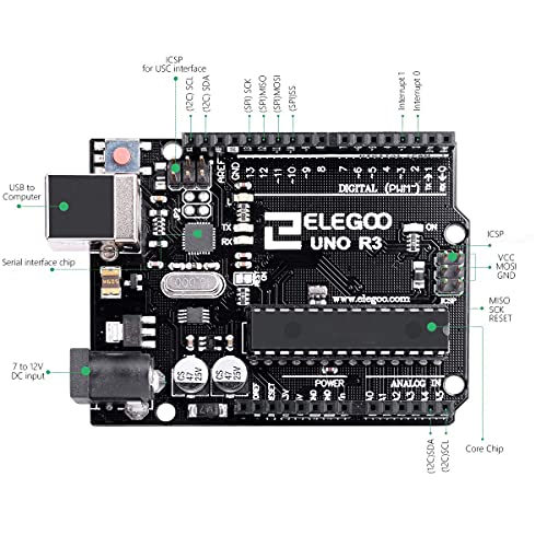
ELEGOO UNO R3 Microcontroller Board: the Arduino board used in the button examples. ELEGOO Dupont Jumper Wire Set, 120-Piece: the jumper wires for the breadboard button wiring.

Sources

Last updated: 2026-11-21. Search volume: not verified. Product links use the store short link form with the product ID; confirm the product slug at publish time.
How Stepper Motors Work: Steps, Coils, and Microstepping

NEMA 17 stepper motor beside a 28BYJ-48 stepper motor and A4988 driver

How Stepper Motors Work: Steps, Coils, and Microstepping

A stepper motor turns in fixed steps instead of spinning freely. A standard NEMA 17 motor has a step angle of 1.8 degrees, so it takes exactly 200 steps to turn one full revolution. Each pulse from the driver moves the rotor one step, so counting pulses tells you exactly how far the shaft has turned, with no encoder.

How stepper motors work: what is a stepper motor?

A stepper motor is a brushless DC motor that divides a full rotation into a fixed number of equal steps. Inside the motor, a stator carries coil windings and a rotor carries a permanent magnet or a toothed iron assembly. When current flows through a pair of stator coils, the magnetic field pulls the rotor into line with the energised coils. When the driver energises the next pair of coils in sequence, the rotor moves one step further round. Keep the coils energised and the motor holds its position firmly, with no brake needed.

A standard NEMA 17 motor has 50 rotor teeth and 4 magnetic field orientations from its two phases, which gives 50 times 4, or 200 steps per revolution. Divide 360 degrees by 200 steps and the step angle is 1.8 degrees. A 0.9 degree motor has 400 steps per revolution and gives finer resolution at the cost of less torque per step.

NEMA 17 describes the mounting face, not the motor performance. NEMA 17 means a 1.7 inch square face, or 42.3 mm square. Two NEMA 17 motors can have very different lengths, torques and currents. Always read the current rating and the holding torque of your exact motor, not just the NEMA size.

How does a stepper differ from a DC motor and a servo?

A DC motor spins freely when power is applied, and its speed depends on voltage and load. It has no built in position, so a robot that needs to know how far a wheel turned must add an encoder. A servo moves to a commanded angle and holds it with a closed loop, but its range is usually limited to 180 degrees. A stepper moves in fixed steps over unlimited rotations, and the step count is the position, so it needs no encoder for open loop positioning.

Spec (unit) DC motor Servo Stepper motor
Motion Continuous rotation Limited angle, usually 180 degrees Fixed steps, unlimited rotation
Position feedback None, add encoder Built in potentiometer None, step count is position
Typical control PWM duty for speed PWM pulse width for angle STEP pulses for distance
Holding torque at rest None without power Holds angle under load Holds position with coils energised
Best for Wheels, fans, pumps Steering, arms, pan tilt 3D printers, CNC, precise positioning

The trade off is speed and efficiency. A stepper draws full current even when it holds still, so it runs hotter and uses more power than a DC motor at rest. A stepper also loses steps when the load exceeds its torque, and because there is no feedback, the controller never knows the steps were lost. Size the motor and the driver for the load with margin, and never trust a stepper position after a stall.

What are unipolar and bipolar steppers?

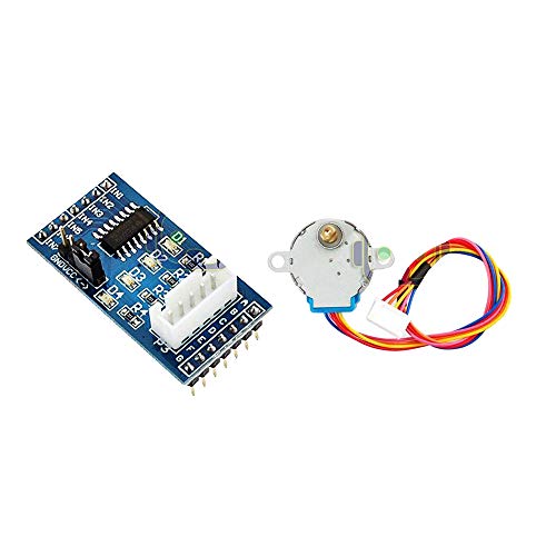
A unipolar stepper has four coils with centre taps, and it is driven by energising one half of each coil at a time. It has five or six wires, and it is simple to drive with a transistor array such as the ULN2003. The 28BYJ-48 is the common unipolar example: a small 5 V geared stepper with a ULN2003 driver board. Unipolar drive is simple, but it uses only half of each coil at a time, so it gives less torque per size than a bipolar motor.

A bipolar stepper has two coils and four wires, with no centre taps. It is driven by an H-bridge that reverses the current through the full coil, which gives 30 to 40 percent more torque than a unipolar motor of the same size. The NEMA 17 is the common bipolar example, and it needs a bipolar driver such as the A4988 or the TMC2208. Bipolar drive is more complex, but it is the standard for 3D printers and CNC machines, where torque matters.

Identify your motor by its wire count before you buy a driver. Five or six wires means unipolar, and a ULN2003 board is the pick. Four wires means bipolar, and an A4988 board is the pick. A four wire motor on a ULN2003 board does not work, and a five wire motor on an A4988 board does not work either.

How does microstepping work?

Microstepping divides each full step into smaller increments by driving the two coils with different currents at the same time. Instead of switching one coil fully on and the other fully off, the driver sets the two coil currents to intermediate values that hold the rotor between two full step positions. The A4988 supports five resolutions, set by its MS1, MS2 and MS3 pins: full step, 1/2 step, 1/4 step, 1/8 step and 1/16 step.

MS1 MS2 MS3 Resolution Steps per revolution (count)
LOW LOW LOW Full step 200
HIGH LOW LOW 1/2 step 400
LOW HIGH LOW 1/4 step 800
HIGH HIGH LOW 1/8 step 1600
HIGH HIGH HIGH 1/16 step 3200

Microstepping makes motion smoother and quieter, and it reduces resonance at low speeds. It does not increase accuracy by the same factor as the step count, because the intermediate positions depend on the exact coil currents and the load. A 1/16 microstep is finer than a full step, but the holding torque at a microstep is lower than at a full step, and the rotor position at a microstep is less exact under load. Use microstepping for smooth motion, not for a promise of 16 times the precision.

How does the 28BYJ-48 work?

The 28BYJ-48 is a geared unipolar stepper. The inner motor takes 32 full steps per turn, at 11.25 degrees per full step, and a gear train of about 64:1 sits behind it, so the output shaft needs about 2,048 steps for one full turn, from 32 times 64. The datasheet ratio is 64:1, so 2,048 is the nominal figure. Teardown counts of the gear teeth give an exact ratio of 63.68395:1, or 283712/4455, on the units counted, which works out to 2037.9 full steps, or 4075.8 half steps, per output turn. The ratio varies by manufacturer, and some units are a true 64:1, so use 2,048 as the nominal value. Over many turns, the small error adds up, so do not use the 28BYJ-48 for long distance odometry without a home sensor.

The 28BYJ-48 runs on 5 V and it is easy to drive with its ULN2003 board, which takes four logic inputs, IN1 to IN4, from the microcontroller. It is slow, under about 15 RPM, and light on torque, but it is ideal for learning, for clocks, for curtain pullers and for a pan tilt head that moves slowly. The standard Arduino Stepper library drives it with 2,048 steps per revolution, and the pin order matters: the sequence 8, 10, 9, 11 is correct for the common wiring, and 8, 9, 10, 11 makes the motor twitch instead of turning.

How does the A4988 driver work?

The A4988, datasheet 4988-DS Rev. 8, April 5, 2022, is a microstepping driver IC from Allegro MicroSystems for bipolar steppers. It drives motors at up to 2 A per coil with proper cooling, and it supports up to 1/16 microstepping. From the microcontroller it needs only two signal pins: STEP, where one pulse advances the motor one microstep, and DIR, where high or low selects the direction. The EN pin enables or disables the driver, and the MS1 to MS3 pins set the microstep resolution.

Setting the current limit correctly is the most important A4988 job. The driver has a small potentiometer that sets Vref, and the current limit follows the formula Vref equals current times 8 times Rsense. Set Vref to about 80 percent of your motor rated current, fit the heatsink, and never power the board with the motor disconnected, because the driver can fail permanently. The motor supply, VMOT, runs from 8 V to 35 V, and a 100 uF capacitor across VMOT close to the board absorbs current spikes.

The A4988 is the standard driver for a NEMA 17 in a 3D printer or a CNC axis. The TMC2208 is the quieter successor, with StealthChop silent operation, but the A4988 is cheaper and its current setting procedure is the one every tutorial covers.

How do you pick a stepper for a project?

Project type Pick this motor Why
Learning, slow pan tilt, clock 28BYJ-48 plus ULN2003 5 V, simple wiring, cheap, 2,048 steps per turn
3D printer axis, CNC axis NEMA 17 plus A4988 200 steps per turn, 1/16 microstepping, high holding torque
Quiet printer axis NEMA 17 plus TMC2208 StealthChop silent stepping, same 200 step motor
Precise positioning, no feedback NEMA 17, 0.9 degree version 400 steps per turn, finer resolution than 1.8 degree

For the drivers behind the motor signals, see L298N vs TB6612 vs DRV8833: Which Motor Driver for Your Robot.

FAQ

How many steps does a NEMA 17 take per revolution?

200 steps at full step, because its step angle is 1.8 degrees and 360 divided by 1.8 is 200. At 1/16 microstepping, it takes 3,200 microsteps per revolution.

Why does my stepper lose steps?

The load exceeds the motor torque, the speed is too high for the torque curve, or the driver current limit is set too low. Reduce the speed, raise the current limit within the motor rating, or use a larger motor.

Can I drive a stepper directly from a GPIO pin?

No. A stepper coil draws far more current than a GPIO pin supplies. Always use a driver board, such as a ULN2003 for a unipolar motor or an A4988 for a bipolar motor, between the pins and the motor.

Does microstepping increase torque?

No. Microstepping makes motion smoother and quieter, but the holding torque at a microstep is lower than at a full step. Use it for smooth motion, not for more torque.

What is the difference between unipolar and bipolar?

A unipolar motor has centre tapped coils and five or six wires, and it is driven by a ULN2003. A bipolar motor has two coils and four wires, and it is driven by an H-bridge such as the A4988. Bipolar gives more torque per size.

Parts used

28BYJ-48 Stepper Motor 5V plus ULN2003 Driver, 2-Set: the geared unipolar stepper for learning and slow positioning. A4988 Stepper Motor Driver: the bipolar microstepping driver for NEMA 17 motors. Nema 17 Stepper Motor: the bipolar stepper for 3D printer and CNC axes.

Sources

Last updated: 2026-11-21. Search volume: not verified. Product links use the store short link form with the product ID; confirm the product slug at publish time.
Mecanum Wheel Robot Car Build: Omni-Directional Drive

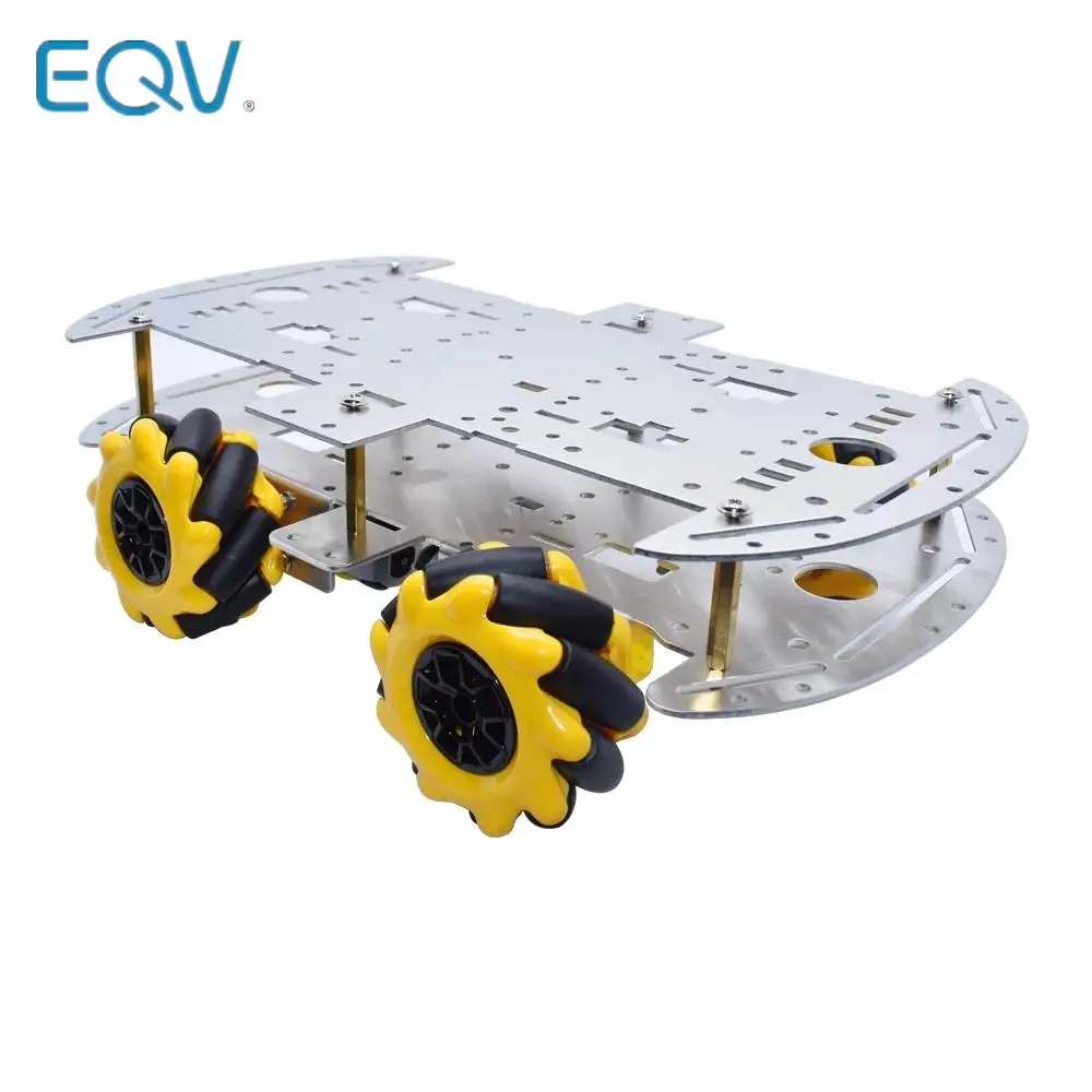
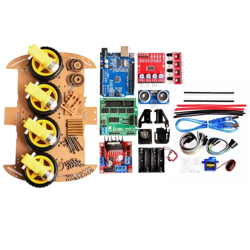
Mecanum wheel robot car chassis with four omni wheels

Mecanum Wheel Robot Car Build: Omni-Directional Drive

Build a mecanum wheel robot car that drives forward, sideways, and diagonally without turning. Each wheel carries rollers set at 45 degrees, and the four wheels spin in matched patterns to strafe. The build uses two L298N drivers, one per wheel pair, because one L298N drives only two motors and a mecanum car has four.

Quick facts

Item Value
Chassis Mecanum 4WD chassis, aluminum alloy, 0.20 feet omni wheels
Drivers 2 x L298N, one per wheel pair
Motors 4 x TT gear motors, 3 to 6 V
Controller ESP32 DevKit V1, 3.3 V logic
Roller angle 45 degrees on each wheel
Moves Forward, back, strafe left, strafe right, rotate, diagonal

Mecanum wheel robot car: how does a wheel move sideways?

A mecanum wheel has small rollers around its rim, each set at 45 degrees to the wheel axle. When the wheel spins, the roller pushes the car partly forward and partly sideways. One wheel alone would slide diagonally, but four wheels in the right pattern cancel the unwanted parts.

For a strafe left, the front left and rear right wheels spin one way while the front right and rear left spin the other way. The forward parts cancel and the sideways parts add. The car slides left without turning. Reverse the pattern and it strafes right. That is the move a normal car cannot make.

Wheel orientation matters. The rollers on the front left and rear right wheels must angle one way, and the rollers on the front right and rear left must angle the other way, forming an X pattern when viewed from above. If one wheel is fitted backward, the car will crab and spin instead of strafing. Check the X before you wire anything.

Why does this build need two L298N drivers?

One L298N drives two DC motors. A mecanum car has four motors, so it needs two L298N modules. Each module drives one diagonal pair: the first drives the front left and rear right wheels, and the second drives the front right and rear left wheels. That pairing matches the strafe pattern and keeps the wiring tidy. Buy the 4WD Kit variant of the chassis kit: it ships with 4 TT gear motors and one L298N, so buy one more L298N for the second pair. The Plate Set variants ship with plates and wheels only, no motors or electronics. The 4WD Kit also includes a UNO R3 board and sensor shield; this build uses an ESP32 DevKit V1 in its place.

Each L298N needs its own enable and direction pins, so the build uses 12 control pins on the ESP32. The ESP32 DevKit V1 has enough GPIO pins for that, but a small board such as a SuperMini would not. Check the pinout post for your exact board before you substitute it.

Both L298N modules share one motor battery. Join the battery positive to both 12 V terminals and the battery negative to both grounds and to the ESP32 ground. Keep the 5 V jumper on at 6 V, and remove it above 12 V, on both modules.

How does the drive mix work?

The drive mix takes three inputs: forward speed, strafe speed, and rotation speed. Each wheel speed is a sum of those three with signs that depend on the wheel position. Front left equals forward plus strafe plus rotation. Front right equals forward minus strafe minus rotation. Rear left equals forward minus strafe plus rotation. Rear right equals forward plus strafe minus rotation.

The sketch below implements that mix for serial control. Type f for forward, s for strafe left, d for strafe right, l to rotate left, r to rotate right, and x to stop. Each key sets the four wheel speeds from the mix, clamps them to -255 to 255, and writes them to the two L298N modules.

Test the mix with the car lifted. Strafe left should spin the front left and rear right wheels one way and the other two the opposite way. If one wheel spins the wrong way, swap its two motor wires at its L298N output. Do not fix wheel direction in code, because the wiring is the fault.

What are the limits of a mecanum car?

Mecanum wheels slip more than normal wheels, because the rollers are always partly sliding. The car will not climb as well, will not push as hard, and will drift on smooth floors. It also draws more current, because two wheels fight each other in every strafe. Expect shorter battery life than a normal 4WD car on the same pack.

The rollers also wear faster than a solid tire, and they pick up grit. Keep the floor clean and the rollers free. A stuck roller turns a mecanum wheel into a bad normal wheel, and the car will crab instead of strafing.

For all that, the strafe is worth it on a bench or a small course. A mecanum car can slide sideways into a gap a normal car cannot reach, and it can rotate in place without a turning circle. That is why warehouse robots and camera dollies use the same wheel.

Wiring

Wire the build with the power off. Check every connection in the table before you connect any battery or USB cable.

From To Notes
Battery box positive Both L298N 12 V terminals Motor supply, 6 V from 4 AA cells
Battery box negative Both L298N GND and ESP32 GND Common ground for both drivers and the logic
L298N A OUT1, OUT2 Front left TT motor First module, left channel
L298N A OUT3, OUT4 Rear right TT motor First module, right channel
L298N B OUT1, OUT2 Front right TT motor Second module, left channel
L298N B OUT3, OUT4 Rear left TT motor Second module, right channel
ESP32 GPIO 25, 27, 14 L298N A ENA, IN1, IN2 Front left motor: PWM, direction A, direction B
ESP32 GPIO 26, 12, 13 L298N A ENB, IN3, IN4 Rear right motor: PWM, direction A, direction B; GPIO 12 is a strapping pin, keep low at boot
ESP32 GPIO 32, 33, 15 L298N B ENA, IN1, IN2 Front right motor: PWM, direction A, direction B
ESP32 GPIO 18, 19, 21 L298N B ENB, IN3, IN4 Rear left motor: PWM, direction A, direction B; GPIO 21 is also I2C SDA, so do not add I2C parts to this build
Both L298N 5 V pins Leave unconnected Jumpers fitted at 6 V; do not feed 5 V in as well
USB 5 V ESP32 USB port Logic supply only; motor current never passes through USB

Power budget

Four TT motors draw more than two. At full load the four motors together draw about 2 to 4 A from the 6 V pack, split across two L298N modules at about 1 to 2 A per module. Each L298N drops about 2 V, so each motor sees about 4 V. The heatsinks on both modules will get warm, so give them airflow.

The ESP32 runs from USB 5 V and draws about 80 to 160 mA. Each L298N logic side draws only a few milliamps from its onboard regulator. The motor battery and the logic supply share only a ground wire. Never power the motors from the ESP32 5 V pin.

A 4 AA alkaline pack sags under a 4 A load, so the car will slow during a strafe. A 5-cell NiMH pack (6 V) holds voltage better than alkalines under load. Do not use a 2-cell lithium pack here: 7.4 V nominal is above the TT motor 3 to 6 V rating. Size the pack for the stall total, not the cruise current.

Build steps

  1. Assemble the mecanum chassis. Fit the four wheels in the X roller pattern: front left and rear right angle one way, front right and rear left the other way.
  2. Mount the two L298N modules and the ESP32 on the top plate. Label the modules A and B before you wire them.
  3. Wire the motors to the L298N outputs from the wiring table. Wire both modules to the same battery and to the ESP32 ground.
  4. Remove all four enable jumpers. Wire the 12 control pins from the wiring table.
  5. Upload the sketch below to the ESP32 DevKit V1. Lift the car off the floor for the first test.
  6. Type f, s, d, l, and r in the serial monitor and confirm each wheel spins the right way for each move.
  7. Set the car on the floor and strafe left and right. If it crabs instead of strafing, one wheel is fitted backward or wired in reverse.

Code

Libraries: none beyond the ESP32 Arduino core. Board: ESP32 DevKit V1. Control from the serial monitor: f forward, b back, s strafe left, d strafe right, l rotate left, r rotate right, x stop.

// Mecanum wheel robot car: 4 motors, 2 x L298N, ESP32
// Board: ESP32 DevKit V1. No extra libraries needed.
// Module A drives front-left (FL) and rear-right (RR).
// Module B drives front-right (FR) and rear-left (RL).
struct MotorPins { int pwm, inA, inB; };
MotorPins FL = {25, 27, 14};  // Module A, channel 1
MotorPins RR = {26, 12, 13};  // Module A, channel 2
MotorPins FR = {32, 33, 15};  // Module B, channel 1
MotorPins RL = {18, 19, 21};  // Module B, channel 2

const int SPEED = 200;  // 0 to 255; TT motors stall below about 80

void driveMotor(MotorPins m, int speed) {
  if (speed >= 0) {
    digitalWrite(m.inA, HIGH);
    digitalWrite(m.inB, LOW);
    analogWrite(m.pwm, speed);
  } else {
    digitalWrite(m.inA, LOW);
    digitalWrite(m.inB, HIGH);
    analogWrite(m.pwm, -speed);
  }
}

void stopAll() {
  driveMotor(FL, 0); driveMotor(FR, 0);
  driveMotor(RL, 0); driveMotor(RR, 0);
}

// Mix: forward, strafe (right is positive), rotation (right is positive).
void mix(int fwd, int strafe, int rot) {
  int fl = constrain(fwd + strafe + rot, -255, 255);
  int fr = constrain(fwd - strafe - rot, -255, 255);
  int rl = constrain(fwd - strafe + rot, -255, 255);
  int rr = constrain(fwd + strafe - rot, -255, 255);
  driveMotor(FL, fl); driveMotor(FR, fr);
  driveMotor(RL, rl); driveMotor(RR, rr);
}

void setup() {
  Serial.begin(115200);
  MotorPins all[4] = {FL, FR, RL, RR};
  for (int i = 0; i < 4; i++) {
    pinMode(all[i].pwm, OUTPUT);
    pinMode(all[i].inA, OUTPUT);
    pinMode(all[i].inB, OUTPUT);
  }
  stopAll();
  Serial.println("Keys: f forward, b back, s strafe left, d strafe right,");
  Serial.println("l rotate left, r rotate right, x stop.");
}

void loop() {
  if (Serial.available() > 0) {
    char c = Serial.read();
    if (c == 'f') mix(SPEED, 0, 0);
    else if (c == 'b') mix(-SPEED, 0, 0);
    else if (c == 's') mix(0, -SPEED, 0);  // Strafe left
    else if (c == 'd') mix(0, SPEED, 0);   // Strafe right
    else if (c == 'l') mix(0, 0, -SPEED);  // Rotate left
    else if (c == 'r') mix(0, 0, SPEED);   // Rotate right
    else if (c == 'x') stopAll();
  }
}

Test and tune it

Lift the car and type s for strafe left. The front left and rear right wheels should spin one way, and the front right and rear left the opposite way. If one wheel is wrong, swap its two motor wires at its L298N output.

Set the car on a hard floor and strafe left 1 foot. The car should slide sideways without turning. If it rotates while strafing, one wheel is fitted backward. Check the X roller pattern from above.

Drive forward 3 feet and mark the end point. Then strafe back to the start. A mecanum car drifts more than a normal car, so expect about 0.25 feet of error. That drift is normal roller slip, not a code fault.

FAQ

Why does my mecanum car need two L298N drivers?

One L298N drives two motors, and a mecanum car has four. Two modules drive one diagonal pair each, which matches the strafe pattern and keeps the wiring tidy.

Why does my mecanum car crab instead of strafing?

One wheel is fitted backward or wired in reverse. Check the X roller pattern from above, then check that each wheel spins the right way for a strafe while the car is lifted.

Why does the car drift sideways when driving forward?

Mecanum rollers always slip a little, and uneven floors make it worse. Small drift is normal. Large drift means one wheel is slower, usually from a loose motor wire or a low battery.

Can I use one driver board with four channels instead?

Yes, if it supplies four independent channels at the motor current. Two L298N modules are the stocked route in this build. A single four-channel MOSFET board is a later upgrade, not a first build change.

How fast can a mecanum car strafe?

Slower than it drives forward, because two wheels fight each other in every strafe and the rollers slip. Keep strafe speed at or below forward speed, and expect shorter battery life than a normal 4WD car.

Parts used

Build it with the Mecanum Wheel 4WD Robot Car Chassis Kit, Aluminum Alloy, 60mm Omni Wheels in the 4WD Kit variant (Single or Double Layer) and one more L298N Dual H-Bridge Motor Driver Module for Arduino (the kit already includes one L298N; one L298N drives two motors, so a four-motor car needs two) and the ESP32 DevKit V1 Development Board, 30-Pin WROOM-32 as the controller. The two-motor version is L298N Robot Car: Wire and Drive Two DC Motors, and the wireless version is ESP-NOW Joystick Robot Car: Two ESP32 Boards, No Router. For the driver comparison, see L298N vs TB6612 vs DRV8833: Which Motor Driver for Your Robot.

Sources

Last updated: 2026-11-21. Search volume: not verified. Product links use the store short link form with the product ID; confirm the product slug at publish time.
L298N Robot Car: Wire and Drive Two DC Motors

Phone showing a BLE control app next to an ESP32 robot car

L298N Robot Car: Wire and Drive Two DC Motors

Wire an L298N between your battery and two TT motors, then drive them from an ESP32 with PWM on the enable pins. The L298N handles up to 2 A per channel, drops about 2 V across the bridge, and needs its own motor supply. The ESP32 only sends low-current direction and speed signals, and the supplies share only a ground.

Quick facts

Item Value
Driver L298N dual H-bridge, 2 A per channel, 3 A peak non-repetitive for 100 ms
Motor supply 5 to 35 V on the module, up to 46 V on the bare chip
Logic supply 4.5 to 7 V; onboard 5 V regulator with jumper
Voltage drop 1.8 to 3.2 V at 1 A, up to 4.9 V at 2 A
Motors 2 x TT 130 gear motors, 3 to 6 V
Speed control PWM on ENA and ENB, 0 to 255

L298N robot car: what does the L298N do?

The L298N is a dual H-bridge driver built on the ST L298 chip. It lets a microcontroller run two DC motors in either direction, at variable speed, from a supply the microcontroller could never deliver itself. Each channel switches up to 2 A of continuous current, with a 3 A peak allowed only non-repetitively for 100 ms.

An H-bridge is four switches arranged so the motor current can flow either way. The IN1 and IN2 pins set the direction for the first motor, and IN3 and IN4 set it for the second. The ENA and ENB pins enable each channel, and a PWM signal on an enable pin sets the speed. With the enable jumpers fitted, each motor runs at full speed whenever the direction pins command movement.

The bridge is built from bipolar transistors, not MOSFETs, so it drops voltage. At 1 A the drop is 1.8 to 3.2 V, and at 2 A it reaches 4.9 V. That drop becomes heat in the chip, which is why the module carries a large heatsink. A 12 V supply gives the motor about 10 V. A 6 V supply gives the motor about 4 V.

When do you remove the 5 V jumper?

The module has an onboard 5 V regulator and a jumper that enables it. With the jumper fitted and a motor supply of 12 V or less, the regulator makes 5 V on the 5 V pin, and you can use that pin to power your logic. With a motor supply above 12 V, remove the jumper first, or the regulator overheats.

With the jumper removed, the 5 V pin becomes an input. You must feed 5 V into it yourself to power the chip logic. This build uses a 6 V motor pack, so the jumper stays on. The regulator then supplies the logic, and the ESP32 runs from its own USB supply.

Never connect two 5 V supplies to the same pin. If the jumper is fitted, leave the 5 V pin unconnected, or the regulator and your other supply will fight. If the jumper is removed, feed 5 V in and do not expect 5 V out.

How do you wire the L298N to an ESP32?

Connect the motor battery positive to the 12 V terminal and the battery negative to GND. Connect the two TT motors to OUT1 and OUT2 for the left motor, and OUT3 and OUT4 for the right motor. Connect ENA, IN1, IN2, ENB, IN3 and IN4 to the ESP32 pins in the wiring table.

The L298N inputs read high from 2.3 V, so the ESP32 3.3 V logic drives them directly. No level shifter is needed. Join the battery negative to the ESP32 ground. Without that common ground, the direction signals have no reference and the motors will not respond.

Remove the ENA and ENB jumpers before you connect PWM. With the jumpers fitted, the enable pins sit at 5 V and the motors run at full speed regardless of your code. With the jumpers removed, the ESP32 PWM signal on each enable pin sets the speed from 0 to 255.

How does PWM speed control work?

PWM switches the enable pin on and off about 1,000 times per second at the core 3.3.13 default of 1 kHz. The motor sees the average voltage, so a 50 percent duty cycle gives about half speed. The sketch below uses analogWrite() with values from 0 to 255. A value of 0 stops the motor, and 255 runs it at full speed for the supply voltage.

TT motors stall at low PWM values. Below about 80 out of 255, many TT motors do not turn at all, because the average voltage cannot overcome friction. Start your speed tests at 150 and work down. If the car creeps at low speed, that is normal for a geared TT motor on an L298N with a 2 V drop.

Direction and speed are separate. The IN pins set forward or reverse, and the enable PWM sets how fast. To stop, set the enable PWM to zero. To brake hard, set both IN pins the same way, but a simple stop is enough for a first build.

Wiring

Wire the build with the power off. Check every connection in the table before you connect any battery or USB cable.

From To Notes
Battery box positive L298N 12 V terminal Motor supply, 6 V from 4 AA cells
Battery box negative L298N GND and ESP32 GND Common ground is required
L298N OUT1, OUT2 Left TT motor Swap these two wires to fix a reversed wheel
L298N OUT3, OUT4 Right TT motor Swap these two wires to fix a reversed wheel
ESP32 GPIO 25 L298N ENA Remove the ENA jumper; PWM speed, left motor
ESP32 GPIO 27 L298N IN1 Left motor direction A
ESP32 GPIO 14 L298N IN2 Left motor direction B
ESP32 GPIO 26 L298N ENB Remove the ENB jumper; PWM speed, right motor
ESP32 GPIO 33 L298N IN3 Right motor direction A; GPIO 33 is used instead of GPIO 12, which is a flash-voltage strapping pin and must stay low at boot
ESP32 GPIO 13 L298N IN4 Right motor direction B
L298N 5 V pin Leave unconnected Jumper fitted at 6 V, so the regulator makes 5 V here; do not feed 5 V in as well
USB 5 V ESP32 USB port Logic supply only; motor current never passes through USB

Power budget

The motors run from 4 AA cells at about 6 V into the L298N. The bridge drops about 2 V, so each TT motor sees about 4 V. Two TT motors at full load draw about 1 to 2 A together, which the L298N handles with its heatsink. At 1 A per channel the chip dissipates about 2 W as heat, so give it airflow and do not cover the heatsink.

The ESP32 runs from USB 5 V and draws about 80 to 160 mA with the radio on. The L298N logic draws about 40 to 60 mA from the motor supply through its onboard regulator. The two supplies share only a ground wire. Never power the motors from the ESP32 5 V pin, and never power the ESP32 from the L298N 5 V pin while USB is also connected, because two 5 V sources will fight.

If you raise the motor supply above 12 V, remove the 5 V jumper first and feed 5 V into the 5 V pin yourself. Above 12 V the onboard regulator overheats. The TT motors in this build are rated 3 to 6 V, so a 6 V pack is the right match and the jumper stays on.

Build steps

  1. Assemble the chassis kit, fit the TT motors and wheels, and mount the L298N and the ESP32 on the top plate.
  2. Connect the motors to OUT1 and OUT2, and OUT3 and OUT4. Connect the battery box to the 12 V terminal and GND. Leave the 5 V jumper on for a 6 V pack.
  3. Remove the ENA and ENB jumpers. Wire the six control pins from the wiring table and join the battery negative to the ESP32 ground.
  4. Upload the sketch below to the ESP32 DevKit V1. Keep the car lifted off the floor for the first test.
  5. Open the serial monitor at 115200 baud and type f, b, l, r, or s, then press Enter. Each key drives the car forward, back, left, right, or stop.
  6. Set the car on the floor and drive it forward. If a wheel runs backward, swap that motor’s two wires at the L298N output.
  7. Test low speed. If the motors stall below a PWM value of about 80, raise your minimum drive speed in the sketch.

Code

Libraries: none beyond the ESP32 Arduino core. Board: ESP32 DevKit V1, Arduino core 3.3.13 (analogWrite arrived in core 3.0). Control the car from the serial monitor: type f, b, l, r, or s and press Enter.

// L298N robot car: two TT motors, PWM speed, serial control
// Board: ESP32 DevKit V1, Arduino core 3.3.13. No extra libraries needed.
const int ENA = 25;  // Left motor PWM (remove the ENA jumper)
const int IN1 = 27;  // Left motor direction A
const int IN2 = 14;  // Left motor direction B
const int ENB = 26;  // Right motor PWM (remove the ENB jumper)
const int IN3 = 33;  // Right motor direction A (GPIO 12 avoided: strapping pin)
const int IN4 = 13;  // Right motor direction B
const int SPEED = 200;  // 0 to 255; TT motors stall below about 80

void driveMotor(int pwmPin, int inA, int inB, int speed) {
  if (speed >= 0) {
    digitalWrite(inA, HIGH);
    digitalWrite(inB, LOW);
    analogWrite(pwmPin, speed);
  } else {
    digitalWrite(inA, LOW);
    digitalWrite(inB, HIGH);
    analogWrite(pwmPin, -speed);
  }
}

void drive(int left, int right) {
  driveMotor(ENA, IN1, IN2, left);
  driveMotor(ENB, IN3, IN4, right);
}

void stopCar() {
  analogWrite(ENA, 0);
  analogWrite(ENB, 0);
}

void setup() {
  Serial.begin(115200);
  pinMode(ENA, OUTPUT); pinMode(IN1, OUTPUT); pinMode(IN2, OUTPUT);
  pinMode(ENB, OUTPUT); pinMode(IN3, OUTPUT); pinMode(IN4, OUTPUT);
  stopCar();
  Serial.println("Type f, b, l, r, or s, then Enter.");
}

void loop() {
  if (Serial.available() > 0) {
    char c = Serial.read();
    if (c == 'f') drive(SPEED, SPEED);        // Forward
    else if (c == 'b') drive(-SPEED, -SPEED); // Reverse
    else if (c == 'l') drive(-SPEED, SPEED);  // Turn left
    else if (c == 'r') drive(SPEED, -SPEED);  // Turn right
    else if (c == 's') stopCar();             // Stop
  }
}

Test and tune it

Lift the car and type f. Both wheels should spin forward at the same speed. If one wheel is slower, check that its motor wires are tight in the screw terminal and that its enable PWM pin is connected.

Type s and confirm both wheels stop within a second. A wheel that keeps spinning has a stuck enable jumper or a shorted IN pin. Remove power and recheck the wiring table.

Drive the car on a hard floor, then on carpet. The car will slow on carpet because the TT motors draw more current under load and the L298N drop grows. That is normal. A MOSFET driver such as the TB6612FNG loses less voltage and is the next step if battery life matters.

FAQ

Why does my L298N get hot?

The bipolar bridge drops about 2 V, and that drop becomes heat. At 1 A per channel the chip dissipates about 2 W. The heatsink is supposed to get warm. Give it airflow and keep the current under 2 A per channel.

Do I remove the 5V jumper on the L298N?

Remove it when the motor supply is above 12 V, because the onboard regulator overheats. Leave it on at 12 V or less. With the jumper removed, feed 5 V into the 5 V pin yourself.

Why do the motors run slow on a 6 V battery?

The L298N drops about 2 V, so a 6 V pack gives each motor about 4 V. That is normal for this driver. A higher supply is not an option here: the pack is already 6 V and the TT motors are rated 3 to 6 V. A MOSFET driver such as the TB6612FNG loses less voltage and gives more speed.

Can the ESP32 drive the L298N directly?

Yes. The L298N inputs read high from 2.3 V, so 3.3 V logic works with no level shifter. Join the battery negative to the ESP32 ground so the signals share a reference.

Why does one wheel spin backward?

That motor is wired in reverse. Swap its two wires at the L298N output terminals. Do not fix it in code, because the wiring is the fault.

Parts used

Build it with the L298N Dual H-Bridge Motor Driver Module for Arduino, the Smart Robot Car Chassis Kit with Speed Encoder and Battery Box for Arduino, 2WD / 4WD, and the TT Motor 130 Gear Motor + 65mm Wheel, 3-6V DC, for Arduino Smart Car Robot, plus the ESP32 DevKit V1 Development Board, 30-Pin WROOM-32 as the controller. The wireless version is ESP-NOW Joystick Robot Car: Two ESP32 Boards, No Router, and the driver comparison is L298N vs TB6612 vs DRV8833: Which Motor Driver for Your Robot. For the driver behind the speed control, see How to Choose the Right Motor Drivers for Arduino Use.

Sources

Last updated: 2026-11-21. Search volume: not verified. Product links use the store short link form with the product ID; confirm the product slug at publish time.
Raspberry Pi Pico Pinout: RP2040 GPIO, ADC, and Power

Raspberry Pi Pico board with 40-pin edge and USB port. Caption: Raspberry Pi Pico board with 40-pin edge. Description: Top view of the Raspberry Pi Pico board used in this pinout guide.

Raspberry Pi Pico Pinout: RP2040 GPIO, ADC, and Power

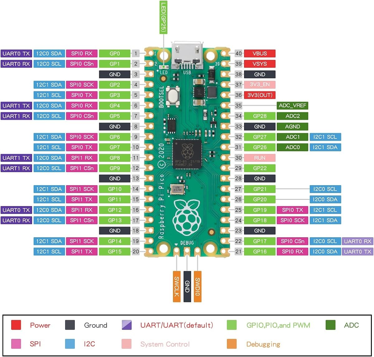
Answer in brief: The Raspberry Pi Pico has 26 GPIO pins, 3 ADC inputs, and PWM on every GPIO pin. It runs the RP2040 chip at a 133 megahertz clock and 3.3 volt logic. This guide maps each pin, the power pins, and the debug pins. It also covers the pins that are not general GPIO.

Quick Facts

Item Detail Source
Chip RP2040, dual-core Cortex-M0+ Raspberry Pi Pico Datasheet
Clock speed 133 megahertz Raspberry Pi Pico Datasheet
Logic voltage 3.3 volts, not 5 volt tolerant Raspberry Pi Pico Datasheet
Board edge 40 pins Raspberry Pi Pico Datasheet
GPIO pins 26 pins: GP0 to GP22 and GP26 to GP28 Raspberry Pi Pico Datasheet
ADC inputs 3 inputs: GP26, GP27, GP28, 12-bit RP2040 Datasheet
ADC range 0 counts to 4095 counts, 0 volts to 3.3 volts RP2040 Datasheet
Onboard LED GP25 Raspberry Pi Pico Datasheet
VSYS input range 1.8 volts to 5.5 volts Raspberry Pi Pico Datasheet
VBUS pin Pin 40, USB 5 volt input Raspberry Pi Pico Datasheet
3V3 output, max 300 milliamperes Raspberry Pi Pico Datasheet
PWM Every GPIO pin, 8 slices RP2040 Datasheet

Raspberry Pi Pico Pinout Table

This table is an original pinout table built from the Raspberry Pi Pico Datasheet. It is not a copied image. The GP names are the printed pin names on the board. The pin numbers are the board edge numbers.

Edge pin GP name Main function Notes
1 GP0 GPIO UART0 TX default
2 GP1 GPIO UART0 RX default
3 GND Ground Common ground
4 GP2 GPIO I2C1 SDA option
5 GP3 GPIO I2C1 SCL option
6 GP4 GPIO UART1 TX, I2C0 SDA default
7 GP5 GPIO UART1 RX, I2C0 SCL default
8 GND Ground Common ground
9 GP6 GPIO I2C1 SDA default
10 GP7 GPIO I2C1 SCL default
11 GP8 GPIO SPI1 RX default
12 GP9 GPIO SPI1 CSn default
13 GND Ground Common ground
14 GP10 GPIO SPI1 SCK default
15 GP11 GPIO SPI1 TX default
16 GP12 GPIO General use
17 GP13 GPIO General use
18 GND Ground Common ground
19 GP14 GPIO General use
20 GP15 GPIO General use
21 GP16 GPIO SPI0 RX default
22 GP17 GPIO SPI0 CSn default
23 GND Ground Common ground
24 GP18 GPIO SPI0 SCK default
25 GP19 GPIO SPI0 TX default
26 GP20 GPIO General use
27 GP21 GPIO General use
28 GND Ground Common ground
29 GP22 GPIO General use
30 RUN Reset Active low, pull low to reset
31 GP26 ADC0 Analog input, 12-bit
32 GP27 ADC1 Analog input, 12-bit
33 AGND Analog ground Ground for ADC use
34 GP28 ADC2 Analog input, 12-bit
35 ADC_VREF ADC reference 3.3 volt reference input
36 3V3(OUT) 3.3 volt output 300 milliamperes max
37 3V3_EN 3.3 volt enable Pull low to disable the regulator
38 GND Ground Common ground
39 VSYS Power input 1.8 volts to 5.5 volts input
40 VBUS Power input USB 5 volt input

Power Pins

Power the Pico through USB, the VBUS pin, or the VSYS pin. USB gives 5 volts to VBUS. VBUS is pin 40 on the board edge. VSYS is pin 39 on the board edge. VSYS accepts 1.8 volts to 5.5 volts. That range covers a battery pack and a 5 volt supply.

Use VSYS for battery power. A 3-cell pack or a single lithium cell with a boost stage can feed VSYS. Check the Pico Datasheet power section before you pick a battery. A battery above 5.5 volts can damage the board. A battery below 1.8 volts will not run the regulator.

The 3V3(OUT) pin is pin 36. It gives 3.3 volts at a max of 300 milliamperes. That value comes from the Raspberry Pi Pico Datasheet. Use it for sensors and small loads. A part that needs more current needs its own regulator.

Pin 37 is 3V3_EN. It enables the 3.3 volt regulator. Leave it alone for normal use. Pull it low only when you want to shut the regulator down. Pin 35 is ADC_VREF. It sets the ADC reference. Leave it at 3.3 volts for normal use.

Boot and Reset Pins

The Pico has a BOOTSEL button for firmware loading. Hold BOOTSEL while you plug in USB. The board then appears as a USB drive. Drag a UF2 file onto that drive to load new firmware. Release BOOTSEL after the drive appears. That path loads MicroPython, CircuitPython, or a C build.

Pin 30 is RUN. It resets the chip when pulled low. It is active low. Connect a button from RUN to ground for a manual reset. Release the button to let the chip run again. Do not hold RUN low for normal use.

ADC Pins

The Pico has 3 ADC inputs on the board edge: GP26, GP27, and GP28. They are ADC0, ADC1, and ADC2. Each input reads 12-bit values from 0 counts to 4095 counts. A 0 volt input reads 0 counts. A 3.3 volt input reads 4095 counts. That step size is about 0.8 millivolts per count at the default reference.

ADC3 is an internal channel. It reads VSYS through GP29. It does not appear on the board edge. Use ADC3 in code to check the supply voltage. That read helps a battery project track its own power.

PWM Pins

PWM works on every GPIO pin on the Pico. The RP2040 chip has 8 PWM slices. Each slice drives 2 pins. That gives 16 PWM channels across the 26 GPIO pins. The Pico Datasheet and the RP2040 Datasheet both list this layout.

PWM drives a signal, not a load. Use a transistor or a driver for a motor. Use a series resistor for an LED. RP2040 GPIO pins have four drive-strength settings, nominally 2, 4, 8, and 12 mA, per the RP2040 Datasheet, section 5.5.3.5. The highest setting is 12 mA per pin. The total current sourced by all GPIO and QSPI pins together must not exceed 50 mA, and the total sunk must not exceed 50 mA, per the same datasheet (IIOVDD_MAX and IIOVSS_MAX). Those are drive-strength modes, not hard per-pin limits, and the pin voltage sags as the load rises. Keep LED current low with a resistor.

I2C Pins

I2C0 uses GP4 for SDA and GP5 for SCL by default. I2C1 uses GP6 for SDA and GP7 for SCL by default. Those defaults are the common pin choices in Pico examples. The RP2040 chip can route I2C to many other pins. Check the RP2040 Datasheet pin function table before you move the bus.

I2C runs at 3.3 volt logic on this board. Check the device voltage before you connect it. A 5 volt I2C device needs a level shifter. A direct 5 volt connection can damage the Pico.

SPI Pins

SPI0 uses GP16 for RX, GP17 for CSn, GP18 for SCK, and GP19 for TX by default. SPI1 uses GP8 for RX, GP9 for CSn, GP10 for SCK, and GP11 for TX by default. Those defaults are the common pin choices in Pico examples. The RP2040 chip can route SPI to many other pins.

SPI runs at 3.3 volt logic on this board. Check the device voltage before you connect it. A 3.3 volt SPI device connects directly. A 5 volt SPI device needs a level shifter.

UART Pins

UART0 uses GP0 for TX and GP1 for RX by default. UART1 uses GP4 for TX and GP5 for RX by default. Those defaults are the common pin choices in Pico examples. The RP2040 chip can route UART to many other pins. Check the RP2040 Datasheet pin function table before you move the port.

The USB port carries a separate serial link for MicroPython and for debug output. That link does not use GP0 or GP1. You can use GP0 and GP1 for a device while the USB console stays open. That split is handy for GPS logging.

USB and SWD Debug Pins

For a Pico comparison, see the live post Raspberry Pi Pico vs Pico W vs Pico 2: Chip, Wireless, and Headers (live post #20577). For starter kit options, see the live post Raspberry Pi Pico Starter Kits Compared: SunFounder, LAFVIN, and More (live post #20579).

Pins to Avoid

Avoid GP23, GP24, GP25, and GP29 as general GPIO. They are internal pins. GP25 is the onboard LED on the Pico. Use it only for the LED. GP24 senses VBUS. GP29 monitors VSYS. GP23 controls power save.

On the Pico WH, GP23, GP24, GP25, and GP29 are used by the onboard wireless chip instead, per the Raspberry Pi Pico W Datasheet. The onboard LED on the Pico WH is driven by the wireless chip, not by GP25, so the GP25 LED blink in the sketch below works on the Pico only, not on the Pico WH. In MicroPython, use Pin(“LED”, Pin.OUT) on the Pico WH.

Avoid 5 volt logic on any GPIO pin. This board uses 3.3 volt logic only. It is not 5 volt tolerant. A 5 volt signal needs a level shifter. A direct 5 volt input can damage the pin.

Max Current and Logic Voltage

Logic voltage is 3.3 volts on every GPIO pin. That value comes from the Raspberry Pi Pico Datasheet. Treat 3.3 volts as the high level. Treat 0 volts as the low level. The board is not 5 volt tolerant. That warning is in the datasheet.

The 3V3(OUT) pin gives 3.3 volts at a max of 300 milliamperes. That value comes from the Raspberry Pi Pico Datasheet. Treat 300 milliamperes as the working limit for that pin. A larger load needs its own regulator.

The RP2040 GPIO pins have four drive-strength settings, nominally 2, 4, 8, and 12 mA, per the RP2040 Datasheet, section 5.5.3.5. The highest setting is 12 mA per pin. The total current sourced by all GPIO and QSPI pins together must not exceed 50 mA, and the total sunk must not exceed 50 mA (IIOVDD_MAX and IIOVSS_MAX). Treat 12 mA per pin and 50 mA total as the working limits.

Use a driver for any load above a small LED. Keep LED current low with a series resistor. A 220 ohm resistor is a common bench value for a 3.3 volt LED test. Check the LED datasheet for its own forward voltage before you pick a resistor.

Wiring and Power Warnings

Power the board before you connect a sensor. Keep the USB cable short. Use a cable under 3 feet for bench tests when you can. Long wires pick up noise. Noise causes ADC jitter and I2C errors.

Do not feed 5 volts into a GPIO pin. Do not feed 5 volts into the 3V3(OUT) pin. Do not feed more than 5.5 volts into VSYS. Each of those mistakes can damage the board. Check the pin labels before every connection.

Pin Test Sketch

Language: MicroPython. Firmware: MicroPython version 1.22.2 for RP2040. No extra library install is needed for this test. Load the firmware with the BOOTSEL drive method. Code status: code not compiled. No arduino-cli or PlatformIO is installed in this environment.

# Raspberry Pi Pico pin test script
# Language: MicroPython version 1.22.2 for RP2040
# Board: Raspberry Pi Pico, RP2040
# Code status: code not compiled

from machine import Pin, ADC, PWM
import time

# Onboard LED is GP25 on the Pico. On the Pico WH the LED is on the wireless chip, not GP25.
led = Pin(25, Pin.OUT)

# ADC test uses GP26, which is ADC0.
adc = ADC(Pin(26))

# PWM test uses GP15 at 1000 hertz.
pwm = PWM(Pin(15))
pwm.freq(1000)  # Set PWM frequency to 1000 hertz.
pwm.duty_u16(0)  # Start with the output off.

# UART test uses UART0 on GP0 TX and GP1 RX.
# The USB console stays free for print output.
from machine import UART
uart = UART(0, baudrate=9600, tx=Pin(0), rx=Pin(1))

print("Pico pin test started")

while True:
    # Read the ADC value on GP26.
    # ADC range is 0 to 65535 counts in MicroPython.
    value = adc.read_u16()
    print("GP26 ADC value:", value)

    # Convert the ADC value to a voltage from 0 to 3.3 volts.
    volts = value * 3.3 / 65535
    print("GP26 volts:", volts)

    # Fade the PWM output on GP15 from off to full.
    for level in range(0, 65536, 4096):
        pwm.duty_u16(level)
        time.sleep(0.05)  # Wait 50 milliseconds per step.

    # Blink the onboard LED on GP25 once per loop.
    led.on()
    time.sleep(0.5)  # Wait 500 milliseconds.
    led.off()
    time.sleep(0.5)  # Wait 500 milliseconds.

Expected result: the console shows a GP26 ADC value and a voltage each loop. The value changes with the voltage on GP26. The PWM output on GP15 fades up in steps. The onboard LED blinks once per loop. If no console output appears, check the MicroPython firmware load and the serial port selection.

Frequently Asked Questions

How many GPIO pins does the Pico have?

It has 26 GPIO pins: GP0 through GP22, plus GP26, GP27, and GP28. GP23, GP24, GP25, and GP29 are internal pins. They do not appear on the board edge as general GPIO.

Which pins are ADC on the Pico?

GP26 is ADC0, GP27 is ADC1, and GP28 is ADC2. Each input reads 12-bit values from 0 counts to 4095 counts. ADC3 is an internal channel that reads VSYS.

Is the Pico 5 volt tolerant?

No, the Pico is not 5 volt tolerant. It uses 3.3 volt logic only. A 5 volt signal needs a level shifter. A direct 5 volt input can damage the pin.

How do I load MicroPython on the Pico?

Hold BOOTSEL while you plug in USB. The board appears as a USB drive. Drag the MicroPython UF2 file onto that drive. The board reboots with MicroPython running.

Boards That Match This Pinout

These boards use the pinout in this guide. Check the product page for current stock before you order. Stock changes over time.

Related reading: compare this board with ESP32 boards in the staged pillar RP2040 vs ESP32 (row 24, staged). For sibling pinouts, see Arduino UNO R3 Pinout and Nano V3.0 USB-C Guide: ATmega328P Board for Arduino IDE.

Sources

  • Raspberry Pi Pico Datasheet, https://datasheets.raspberrypi.com/pico/pico-datasheet.pdf
  • RP2040 Datasheet, https://datasheets.raspberrypi.com/rp2040/rp2040-datasheet.pdf
  • Raspberry Pi Pico W Datasheet, https://pip.raspberrypi.com/documents/RP-008312-DS-pico-w-datasheet.pdf
  • Raspberry Pi Pico pinout guide, https://www.raspberrypi.com/documentation/microcontrollers/raspberry-pi-pico.html

Last updated 2026-11-21.

Arduino UNO R3 Pinout: Digital, Analog, PWM, and Power

Push button wired to an Arduino input pin with a 10k pull-up resistor

Arduino UNO R3 Pinout: Digital, Analog, PWM, and Power

Answer in brief: The Arduino UNO R3 has 14 digital pins, 6 analog inputs, and 6 PWM pins. It runs on 5 volt logic at a 16 megahertz clock. This guide maps each pin, the power pins, and the current limits. It also covers I2C, SPI, UART, and the pins to avoid.

Quick Facts

Item Detail Source
Chip ATmega328P Arduino UNO R3 documentation
Clock speed 16 megahertz Arduino UNO R3 documentation
Logic voltage 5 volts Arduino UNO R3 documentation
Digital pins 14 pins, D0 to D13 Arduino UNO R3 documentation
PWM pins 6 pins: D3, D5, D6, D9, D10, D11 Arduino UNO R3 documentation
Analog inputs 6 inputs, A0 to A5, 10-bit Microchip ATmega328P datasheet DS40002061B
Analog range 0 counts to 1023 counts Microchip ATmega328P datasheet DS40002061B
Per-pin current, recommended 20 milliamperes Microchip ATmega328P datasheet DS40002061B
Per-pin current, absolute max 40 milliamperes Microchip ATmega328P datasheet DS40002061B
Chip total current 200 milliamperes Microchip ATmega328P datasheet DS40002061B
3V3 output, max About 50 milliamperes Arduino UNO R3 documentation
VIN range, recommended 7 volts to 12 volts Arduino UNO R3 documentation

Arduino UNO R3 Pinout Table

This table is an original pinout table built from the Arduino UNO R3 documentation. It is not a copied image. The D names are the printed header names on the board. Use the table with the board in front of you.

Pin Function Shared functions
D0 Digital I/O UART RX
D1 Digital I/O UART TX
D2 Digital I/O Interrupt INT0
D3 Digital I/O, PWM Interrupt INT1, PWM at 490 hertz
D4 Digital I/O None
D5 Digital I/O, PWM PWM at 980 hertz
D6 Digital I/O, PWM PWM at 980 hertz
D7 Digital I/O None
D8 Digital I/O None
D9 Digital I/O, PWM PWM at 490 hertz
D10 Digital I/O, PWM SPI SS, PWM at 490 hertz
D11 Digital I/O, PWM SPI MOSI, PWM at 490 hertz
D12 Digital I/O SPI MISO
D13 Digital I/O SPI SCK, onboard LED
A0 Analog input Digital pin D14
A1 Analog input Digital pin D15
A2 Analog input Digital pin D16
A3 Analog input Digital pin D17
A4 Analog input Digital pin D18, I2C SDA
A5 Analog input Digital pin D19, I2C SCL
VIN Power input 7 volts to 12 volts recommended
5V Power output 5 volt rail from USB or regulator
3V3 Power output 3.3 volt output, about 50 milliamperes max
GND Ground Common ground for all wiring
IOREF Reference Board logic voltage, 5 volts
AREF Reference Analog reference input
RESET Reset Pull low to restart the chip

Power Pins

Power the UNO R3 through USB, the barrel jack, or the VIN pin. The barrel jack and VIN accept 7 volts to 12 volts. The on-board regulator drops that input to 5 volts. A higher input makes the regulator run hotter. Keep the input near 9 volts for bench work when you can.

The 5V pin is a 5 volt output when USB or the jack powers the board. It can also act as a 5 volt input. Feed it only with a clean, regulated 5 volt supply. Do not feed it with a higher voltage. The 3V3 pin gives 3.3 volts at about 50 milliamperes max. Use it only for small 3.3 volt parts.

IOREF tells a shield the board logic voltage. On this board, IOREF is 5 volts. AREF sets the top of the analog range. Leave AREF unconnected for normal use. The default reference is 5 volts. Ground pins appear on both headers. Use the nearest ground for each part.

Boot and Reset Pins

The UNO R3 has no strapping pins like an ESP32 board. It starts code on power-up or reset. The RESET pin restarts the chip when pulled low. The on-board RESET button does the same job. A shield can also pull RESET low.

Uploads use the USB port and the on-board USB-to-serial chip. The IDE resets the board through the serial link. No jumper is needed for normal uploads. If an upload fails, press RESET once and try again. Check the board and port selection in the IDE first.

The ICSP header near the chip carries SPI and reset for direct programming. Most users never need it. Leave it alone unless you program the chip with an external programmer. A wrong ICSP connection can erase the bootloader.

ADC Pins

The UNO R3 has 6 analog inputs, A0 through A5. Each input reads 10-bit values from 0 counts to 1023 counts. A 0 volt input reads 0 counts. A 5 volt input reads 1023 counts. That step size is about 4.9 millivolts per count at the default reference.

A0 through A5 also work as digital pins D14 through D19. Use them as digital outputs when you run out of digital pins. Set the pin mode in code. A pin cannot read analog and drive digital at the same time.

PWM Pins

PWM is available on 6 pins: D3, D5, D6, D9, D10, and D11. The PWM frequency is 490 hertz on D3, D9, D10, and D11. It is 980 hertz on D5 and D6. That split matters for some loads. A motor driver may buzz at one frequency and run smooth at the other.

PWM drives a signal, not a load. Use a transistor or a driver for a motor. Use a series resistor for an LED. A PWM pin still follows the 20 milliampere recommended limit. Do not connect a motor directly to a PWM pin.

I2C Pins

I2C uses A4 for SDA and A5 for SCL. Those two analog pins carry the bus. Connect a display or a sensor to those two pins. Share the bus with more than one device when each device has a different address.

A4 and A5 cannot read analog while they run the I2C bus. Plan the pin budget when you need both I2C and analog reads. Use A0 through A3 for analog in that case. That leaves A4 and A5 free for the bus.

SPI Pins

SPI uses D10 for SS, D11 for MOSI, D12 for MISO, and D13 for SCK. Those four pins carry the bus. Pick a different digital pin for a second chip select when you add a second SPI device. D10 must stay an output for the board to act as SPI master.

SPI runs at 5 volt logic on this board. Check the device voltage before you connect it. A 3.3 volt SPI device needs a level shifter. A direct 5 volt connection can damage a 3.3 volt part.

UART Pins

UART uses D0 for RX and D1 for TX. Those pins connect to the USB-to-serial chip. They carry the serial monitor link. They also carry uploads. Do not connect a GPS module to D0 and D1 while you debug over USB. The two uses clash.

Keep the baud rate the same on both ends of a UART link. A mismatch gives garbled text. Start at 9600 baud for a new device. Raise the rate only after the link works.

USB Pins

The UNO R3 has a USB port for power and programming. The product in this guide uses a USB cable in the box. Check the product page for the cable type in your pack. The USB link powers the board at 5 volts. It also carries uploads and serial debug output.

The USB port does not expose D0 and D1 as separate pads. Those pins are the UART lines behind the USB chip. Treat D0 and D1 as busy during uploads. Free them only after the upload ends.

Pins to Avoid

Avoid D0 and D1 for sensors while you debug over USB. Avoid A4 and A5 for analog reads while I2C is active. Avoid D10 as a general input when SPI runs as master. It must stay an output in that mode.

Avoid AREF as a power output. It is a reference input only. Avoid feeding 5 volts into the 3V3 pin. Avoid feeding more than 5 volts into the 5V pin. Both mistakes can damage the regulator or the chip.

Avoid a load above 20 milliamperes on any single pin. Avoid a total load above 200 milliamperes across the chip. Those limits come from the Microchip ATmega328P datasheet DS40002061B. Stay under them for a long board life.

Max Current and Logic Voltage

Logic voltage is 5 volts on every digital pin. That value comes from the Arduino UNO R3 documentation. Treat 5 volts as the high level. Treat 0 volts as the low level. A 3.3 volt sensor output may read as high on a 5 volt input, but check the sensor datasheet first.

The recommended current per pin is 20 milliamperes. The absolute max per pin is 40 milliamperes. The chip total is 200 milliamperes. Those three numbers come from the Microchip ATmega328P datasheet DS40002061B. Treat 20 milliamperes as the working limit. Treat 40 milliamperes as a damage threshold, not a target.

The 3V3 output gives about 50 milliamperes max. That value comes from the Arduino UNO R3 documentation. Use it only for small 3.3 volt parts. A WiFi module or a large display needs its own regulator.

Wiring and Power Warnings

Power the board before you connect a sensor. Keep the USB cable short. Use a cable under 3 feet for bench tests when you can. Long wires pick up noise. Noise causes analog jitter and I2C errors.

Use a series resistor for every LED. A 220 ohm resistor is a common bench value for a 5 volt LED test. Check the LED datasheet for its own forward voltage before you pick a resistor. A LED with no resistor can draw too much current from the pin.

Use a driver for any motor, relay, or solenoid. The GPIO pin only signals the driver. The driver handles the load current. A direct motor connection can damage the pin and reset the board.

Pin Test Sketch

Language: Arduino. Library: Arduino AVR core version 1.8.6, with no extra library install. Code status: code not compiled. No arduino-cli or PlatformIO is installed in this environment.

// Arduino UNO R3 pin test sketch
// Board: UNO R3, ATmega328P
// Arduino AVR core version 1.8.6
// Code status: code not compiled

// PWM test pin is D9. It runs at 490 hertz.
const int pwmPin = 9;
// Analog test pin is A0. It reads 0 to 1023 counts.
const int analogPin = A0;
// Onboard LED pin is D13.
const int ledPin = 13;

void setup() {
  // Start serial at 9600 baud for debug output.
  Serial.begin(9600);
  delay(500); // Wait 500 milliseconds for the monitor.

  // Set the PWM pin and the LED pin as outputs.
  pinMode(pwmPin, OUTPUT);
  pinMode(ledPin, OUTPUT);

  Serial.println("UNO R3 pin test started");
}

void loop() {
  // Read the analog value on A0.
  int adcValue = analogRead(analogPin);
  Serial.print("A0 value: ");
  Serial.println(adcValue);

  // Fade the PWM output on D9 from off to full.
  for (int level = 0; level <= 255; level += 5) {
    analogWrite(pwmPin, level);
    delay(20); // Wait 20 milliseconds per step.
  }

  // Blink the onboard LED on D13 once per loop.
  digitalWrite(ledPin, HIGH);
  delay(500); // Wait 500 milliseconds.
  digitalWrite(ledPin, LOW);
  delay(500); // Wait 500 milliseconds.
}

Expected result: the serial monitor shows an A0 value each loop. The value changes with the voltage on A0. The PWM output on D9 fades up in steps. The onboard LED blinks once per loop. If no serial output appears, check the board and port selection in the IDE.

Frequently Asked Questions

How many digital pins does the UNO R3 have?

It has 14 digital pins, D0 through D13. Six of those pins support PWM. The analog pins A0 through A5 can also work as digital pins D14 through D19.

Which pins are PWM on the UNO R3?

PWM pins are D3, D5, D6, D9, D10, and D11. D5 and D6 run at 980 hertz. The other four PWM pins run at 490 hertz.

What is the current limit per pin?

The recommended limit is 20 milliamperes per pin. The absolute max is 40 milliamperes per pin. The chip total is 200 milliamperes. Stay under the recommended limit for normal use.

Can I power the UNO R3 from the VIN pin?

Yes, feed VIN with 7 volts to 12 volts. The on-board regulator drops that input to 5 volts. Keep the input near 9 volts for bench work. A higher input makes the regulator run hotter.

Boards That Match This Pinout

These boards use the pinout in this guide. Check the product page for current stock before you order. Stock changes over time.

Related reading: compare this board with other microcontroller families in the staged pillar RP2040 vs ESP32 (row 24, staged). For a first project, see the live post How to Start with a UNO R3 Board for Arduino Projects (live post #15177) and the live post How to Build Your First Arduino Project with UNO and OLED (live post #15203). For sibling pinouts, see Nano V3.0 USB-C Guide: ATmega328P Board for Arduino IDE and Raspberry Pi Pico Pinout.

Sources

  • Arduino UNO R3 documentation, https://docs.arduino.cc/hardware/uno-rev3/
  • Microchip ATmega328P datasheet DS40002061B, https://ww1.microchip.com/downloads/en/DeviceDoc/Atmel-7810-Automotive-Microcontrollers-ATmega328P_Datasheet.pdf
  • Arduino UNO R3 schematic, https://docs.arduino.cc/hardware/uno-rev3/

Last updated 2026-11-21.

ESP32-CAM Pinout: Camera, SD Card, and Free GPIO Pins

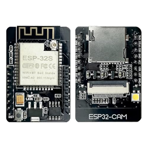
ESP32-CAM board with OV2640 camera module and pin headers. Caption: ESP32-CAM board with OV2640 camera module. Description: Front view of the ESP32-CAM board used in this pinout guide.

ESP32-CAM Pinout: Camera, SD Card, and Free GPIO Pins

Answer in brief: The ESP32-CAM uses most of its GPIO pins for the camera and the microSD card. Only a small set of pins stays free for sensors and outputs. This guide maps the camera pins, the SD card pins, and the free pins. It also covers power, boot mode, and safe wiring.

Quick Facts

Item Detail Source
Board AI-Thinker ESP32-CAM Espressif ESP32 Series Datasheet
Logic voltage 3.3 volts Espressif ESP32 Series Datasheet
USB port None on board ESP32-CAM camera driver pin map
Programming pins GPIO1 TX and GPIO3 RX ESP32-CAM camera driver pin map
Flash mode pin GPIO0 held low at reset ESP32-CAM camera driver pin map
Camera pins used 15 pins ESP32-CAM camera driver pin map
SD card pins in 4-bit mode 6 pins ESP32-CAM camera driver pin map
SD card pins in 1-bit mode 3 pins ESP32-CAM camera driver pin map
Free pins with no SD card 6 pins ESP32-CAM camera driver pin map

ESP32-CAM Pinout Table

This table is an original pinout table built from the source data listed below. It is not a copied image. Check the board print against this table before you wire anything. Some boards print VCC on one header and 5V on the other header.

Header pin label GPIO Function Notes
5V Power 5 volt input Use a stable 5 volt supply
GND Power Ground Common ground for all wiring
GPIO12 GPIO12 SD DATA2, ADC, touch Free only when SD card is not used
GPIO13 GPIO13 SD DATA3, ADC, touch Free only when SD card is not used
GPIO15 GPIO15 SD CMD, ADC, touch, strapping Free only when SD card is not used
GPIO14 GPIO14 SD CLK, ADC, touch Free only when SD card is not used
GPIO2 GPIO2 SD DATA0, ADC, touch, strapping Free only when SD card is not used
GPIO4 GPIO4 SD DATA1, ADC, touch Free only when SD card is not used
3V3 Power 3.3 volt output Do not use as a 5 volt input
GPIO16 GPIO16 PSRAM chip select Do not use for other wiring
GPIO0 GPIO0 Camera XCLK, strapping, boot Hold low at reset for flash mode
GND Power Ground Common ground for all wiring
VCC Power 5 volt input Same 5 volt rail as the 5V pin
U0R GPIO3 UART receive Connect to adapter TX for programming
U0T GPIO1 UART transmit Connect to adapter RX for programming
GND Power Ground Common ground for all wiring

Power Pins

The board takes 5 volts through the 5V pin or the VCC pin. Both pins sit on the same 5 volt rail on this board. Use one 5 volt input at a time. Do not feed 5 volts into the 3V3 pin. That mistake can damage the board.

Strapping and Boot Pins

GPIO0 controls flash mode. Hold GPIO0 low at reset to enter flash mode. Release it after programming starts. Normal run mode needs GPIO0 high or floating at reset. A jumper wire to ground works for this step. Remove the jumper after the upload.

GPIO0 also carries the camera clock, XCLK. That dual role is normal on this board. Do not add a permanent pull-down to GPIO0. A permanent pull-down would force flash mode at every reset. Use a temporary jumper only during programming.

GPIO2 and GPIO15 are also strapping pins. They share SD card duties on this board. Keep them free of strong pull-downs at boot when the SD card is in use. Check the Espressif ESP32 Series Datasheet for the full strapping table before you add boot-time wiring.

Camera Pins

The camera uses 15 pins on this board. Those pins are fixed. Do not reassign them to other parts. The list below is the camera driver pin map for the AI-Thinker board.

Camera signal GPIO Notes
Data D0 GPIO5 Camera data line
Data D1 GPIO18 Camera data line
Data D2 GPIO19 Camera data line
Data D3 GPIO21 Camera data line
Data D4 GPIO36 Camera data line, input only
Data D5 GPIO39 Camera data line, input only
Data D6 GPIO34 Camera data line, input only
Data D7 GPIO35 Camera data line, input only
XCLK GPIO0 Camera clock, also boot pin
PCLK GPIO22 Camera pixel clock
VSYNC GPIO25 Camera vertical sync
HREF GPIO23 Camera horizontal reference
SDA GPIO26 Camera control bus data
SCL GPIO27 Camera control bus clock
PWDN GPIO32 Camera power down control

SD Card Pins

The microSD slot uses 6 pins in 4-bit mode. That mode gives the fastest SD writes on this board. The 6 pins are GPIO14, GPIO15, GPIO2, GPIO4, GPIO12, and GPIO13. All 6 pins are then busy. No free GPIO remains from that set while 4-bit mode runs.

SD signal GPIO Mode
CLK GPIO14 4-bit and 1-bit
CMD GPIO15 4-bit and 1-bit
DATA0 GPIO2 4-bit and 1-bit
DATA1 GPIO4 4-bit only
DATA2 GPIO12 4-bit only
DATA3 GPIO13 4-bit only

Free GPIO Pins

Free pins depend on SD card use. With no SD card, 6 pins are free. Those pins are GPIO2, GPIO4, GPIO12, GPIO13, GPIO14, and GPIO15. With 1-bit SD mode, 3 pins are free. Those pins are GPIO4, GPIO12, and GPIO13. With 4-bit SD mode, none of those 6 pins are free.

GPIO33 is the red LED pin. You can blink it in code. It is not a good general output for a load. GPIO16 is the PSRAM chip select. Leave GPIO16 alone. GPIO32 is the camera power-down pin. Leave it under camera driver control.

ADC, Touch, and PWM

GPIO2, GPIO4, GPIO12, GPIO13, GPIO14, and GPIO15 all support ADC input. They also support touch input on the ESP32 chip. That overlap is useful. It is also a limit. A pin in SD use cannot serve as an ADC input at the same time.

I2C, SPI, and UART

The camera control bus uses GPIO26 for SDA and GPIO27 for SCL. Those pins are busy. Do not add a second I2C device on the same two pins without checking the camera driver first. A shared bus can clash with camera control.

USB and Programming

This board has no USB port. Program it with a 3.3 volt USB-to-serial adapter. Set the adapter to 3.3 volts. A 5 volt adapter setting can damage the 3.3 volt logic. Check the adapter jumper before every upload.

Connect adapter TX to board U0R, which is GPIO3. Connect adapter RX to board U0T, which is GPIO1. Connect ground to ground. Connect adapter 3.3 volt output only if the adapter can supply enough current. A separate 5 volt supply on the 5V pin is often more stable.

Hold GPIO0 low. Press reset. Start the upload. Release GPIO0 after the upload starts. Remove the GPIO0 jumper after the upload ends. Press reset once more to run the new code. For a full setup walkthrough, see the live post How to Start with ESP32-CAM for WiFi Camera Projects (live post #15173). For the flash steps in detail, see the live post ESP32-CAM Flashing and First Camera Stream: From Unboxing to WiFi Video (live post #22720).

Pins to Avoid

Avoid GPIO16 for any new wiring. It is the PSRAM chip select. Avoid GPIO32 for general use. It controls camera power down. Avoid GPIO0 as a permanent output. It is the boot pin and the camera clock.

Avoid GPIO36, GPIO39, GPIO34, and GPIO35 as outputs. They are input-only pins. Avoid GPIO6 through GPIO11. Those pins connect to the on-board flash memory. They do not appear on the headers. Do not try to use them.

Avoid 5 volt logic on any GPIO pin. This board uses 3.3 volt logic. A 5 volt signal needs a level shifter. A direct 5 volt input can damage the pin.

Max Current and Logic Voltage

Logic voltage is 3.3 volts on every GPIO pin. That value comes from the Espressif ESP32 Series Datasheet. Treat 3.3 volts as the high level. Treat 0 volts as the low level. Keep sensor outputs at 3.3 volts or below.

At the strongest drive setting, a GPIO pin sources about 40 mA (IOH) and sinks about 28 mA (IOL), per Table 5-4 of the Espressif ESP32 Series Datasheet v5.3. Those are drive-strength values at 3.3 volts, not a recommended continuous load. Cumulative IO output current for the chip is 1200 mA at absolute maximum, per section 5.1 of the same datasheet. Treat a small LED through a resistor as the practical per-pin load, not 40 mA.

Use a transistor or a driver for any load above a small LED. Keep LED current low with a series resistor. A 220 ohm resistor is a common bench value for a 3.3 volt LED test. Check the LED datasheet for its own forward voltage before you pick a resistor.

Wiring and Power Warnings

Power the board before you connect a 5 volt sensor. Keep the USB-to-serial adapter at 3.3 volts. Double-check the adapter jumper. A wrong jumper is a fast way to damage the board.

Keep wires short. Use a cable under 3 feet for bench tests when you can. Long wires pick up noise. Noise causes SD errors and camera glitches. Twist power and ground wires together when the run is long.

Pin Test Sketch

Language: Arduino. Library: Arduino ESP32 core version 2.0.14, with the built-in esp_camera driver. No extra library install is needed for this test. Code status: code not compiled. No arduino-cli or PlatformIO is installed in this environment.

// ESP32-CAM pin test sketch
// Board: AI-Thinker ESP32-CAM
// Arduino ESP32 core version 2.0.14
// Code status: code not compiled

#include "esp_camera.h"

// Camera pin map for the AI-Thinker board.
#define PWDN_GPIO_NUM 32
#define RESET_GPIO_NUM -1
#define XCLK_GPIO_NUM 0
#define SIOD_GPIO_NUM 26
#define SIOC_GPIO_NUM 27
#define Y9_GPIO_NUM 35
#define Y8_GPIO_NUM 34
#define Y7_GPIO_NUM 39
#define Y6_GPIO_NUM 36
#define Y5_GPIO_NUM 21
#define Y4_GPIO_NUM 19
#define Y3_GPIO_NUM 18
#define Y2_GPIO_NUM 5
#define VSYNC_GPIO_NUM 25
#define HREF_GPIO_NUM 23
#define PCLK_GPIO_NUM 22

// Free pin test uses GPIO4 when no SD card is fitted.
// GPIO4 is SD DATA1 in 4-bit mode, so remove the card first.
const int testPin = 4;

void setup() {
  // Start serial at 115200 baud for debug output.
  Serial.begin(115200);
  delay(1000); // Wait 1 second for the monitor to open.

  // Set the test pin as an output and blink the red LED pin.
  pinMode(testPin, OUTPUT);
  pinMode(33, OUTPUT);

  // Start the camera with a small frame size for the test.
  camera_config_t config;
  config.ledc_channel = LEDC_CHANNEL_0;
  config.ledc_timer = LEDC_TIMER_0;
  config.pin_d0 = Y2_GPIO_NUM;
  config.pin_d1 = Y3_GPIO_NUM;
  config.pin_d2 = Y4_GPIO_NUM;
  config.pin_d3 = Y5_GPIO_NUM;
  config.pin_d4 = Y6_GPIO_NUM;
  config.pin_d5 = Y7_GPIO_NUM;
  config.pin_d6 = Y8_GPIO_NUM;
  config.pin_d7 = Y9_GPIO_NUM;
  config.pin_xclk = XCLK_GPIO_NUM;
  config.pin_pclk = PCLK_GPIO_NUM;
  config.pin_vsync = VSYNC_GPIO_NUM;
  config.pin_href = HREF_GPIO_NUM;
  config.pin_sccb_sda = SIOD_GPIO_NUM;
  config.pin_sccb_scl = SIOC_GPIO_NUM;
  config.pin_pwdn = PWDN_GPIO_NUM;
  config.pin_reset = RESET_GPIO_NUM;
  config.xclk_freq_hz = 20000000; // 20 megahertz camera clock.
  config.pixel_format = PIXFORMAT_JPEG;
  config.frame_size = FRAMESIZE_QVGA; // Small size for a fast test.
  config.jpeg_quality = 12; // Lower number means higher quality.
  config.fb_count = 1;

  // Report the camera start result on serial.
  esp_err_t err = esp_camera_init(&config);
  if (err != ESP_OK) {
    Serial.printf("Camera init failed, error 0x%x\n", err);
    return;
  }
  Serial.println("Camera init OK");
}

void loop() {
  // Blink the test pin and the red LED pin in turn.
  digitalWrite(testPin, HIGH);
  digitalWrite(33, LOW);
  delay(500); // Wait 500 milliseconds.
  digitalWrite(testPin, LOW);
  digitalWrite(33, HIGH);
  delay(500); // Wait 500 milliseconds.
  Serial.println("Pin test tick");
}

Expected result: the serial monitor shows “Camera init OK” and then a tick line each 1 second. The red LED blinks in turn with the test pin. If camera init fails, check the ribbon cable seating first. Then check the 5 volt supply.

Frequently Asked Questions

How many free GPIO pins does the ESP32-CAM have?

It has 6 free pins with no SD card. The pins are GPIO2, GPIO4, GPIO12, GPIO13, GPIO14, and GPIO15. The count drops to 3 pins in 1-bit SD mode. It drops to 0 pins from that set in 4-bit SD mode.

Can I use GPIO0 as a normal output?

No, not as a normal output. GPIO0 is the boot pin and the camera clock. It must be high at reset for normal run mode. Use a free pin from the SD set instead.

Why does my ESP32-CAM reset when WiFi starts?

A weak 5 volt supply is the most common cause. WiFi draws a current spike at start. Use a stable 5 volt supply rated at 1 ampere or more. Keep wires short and check the ground.

Does the ESP32-CAM have a USB port?

No, it has no USB port. Program it with a 3.3 volt USB-to-serial adapter. Connect adapter TX to U0R and adapter RX to U0T. Hold GPIO0 low at reset for flash mode.

Boards That Match This Pinout

These boards use the pinout in this guide. Check the product page for current stock before you order. Stock changes over time.

Related reading: compare this board with the wider ESP32 family in the staged pillar ESP32 vs ESP32-S3 vs ESP32-C3 vs ESP32-C6 (row 22, staged). For sibling pinouts, see How to Use the ESP32 DevKit V1 Board for WiFi Projects and XIAO ESP32S3 Pinout.

Sources

  • Espressif ESP32 Series Datasheet v5.3, https://www.espressif.com/sites/default/files/documentation/esp32_datasheet_en.pdf
  • ESP32-CAM camera driver pin map, Espressif Arduino ESP32 core, https://github.com/espressif/arduino-esp32/blob/master/libraries/ESP32/examples/Camera/CameraWebServer/camera_pins.h

Last updated 2026-11-21.

ESP32-S2 Mini Pinout: GPIO, USB OTG, and ADC

ESP32-S2 Mini development board with USB-C port and pin headers. Caption: ESP32-S2 Mini board, front view with USB-C port. Description: Top view of the ESP32-S2 Mini board used in this pinout guide.

ESP32-S2 Mini Pinout Guide: GPIO, USB OTG, and ADC

The ESP32-S2 Mini pinout starts with one clear limit: this chip has WiFi only, and it has no Bluetooth. The ESP32-S2 chip has 43 GPIO pins. It runs a single-core Xtensa LX7 core at 240 MHz. Native USB OTG uses GPIO19 and GPIO20. DAC uses GPIO17 and GPIO18.

Quick facts

Item Value Source
Chip GPIO count 43 GPIO pins ESP32-S2 Series Datasheet
Core Single-core Xtensa LX7 at 240 MHz ESP32-S2 Series Datasheet
Radios WiFi only, no Bluetooth ESP32-S2 Series Datasheet
Logic voltage 3.3 volts ESP32-S2 Series Datasheet
USB OTG pins GPIO19 D- and GPIO20 D+ ESP32-S2 Series Datasheet
ADC1 pins GPIO1 to GPIO10 ESP32-S2 Series Datasheet
ADC2 pins GPIO11 to GPIO20 ESP32-S2 Series Datasheet
DAC pins GPIO17 and GPIO18 ESP32-S2 Series Datasheet
UART0 pins GPIO43 TX and GPIO44 RX ESP32-S2 Series Datasheet
Strapping pins GPIO0, GPIO45, GPIO46 ESP32-S2 Series Datasheet
Module GPIO count 37 GPIO pins on ESP32-S2-MINI-2 ESP32-S2-MINI-2 Datasheet v1.4
Module flash 4 MB flash, optional 2 MB PSRAM ESP32-S2-MINI-2 Datasheet v1.4

ESP32-S2 Mini pinout table

Use this table as the chip reference. Match each GPIO number to the silkscreen on your board before you wire it.

GPIO Main role Notes
GPIO0 Strapping and boot Hold low at reset for download mode
GPIO1 to GPIO10 ADC1 channels 0 to 9 Analog input, 3.3 volt max
GPIO11 to GPIO16 ADC2 channels 0 to 5 ADC2 shares use with WiFi
GPIO17 ADC2 channel 6, DAC channel 1 True analog output pin
GPIO18 ADC2 channel 7, DAC channel 2 True analog output pin
GPIO19 ADC2 channel 8, USB OTG D- Native USB, not an ADC pin in use
GPIO20 ADC2 channel 9, USB OTG D+ Native USB, not an ADC pin in use
GPIO21 to GPIO32 General GPIO Check board silkscreen for exposure
GPIO33 to GPIO42 General GPIO Check board silkscreen for exposure
GPIO43 UART0 TX Serial transmit pin
GPIO44 UART0 RX Serial receive pin
GPIO45 Strapping Check level at boot
GPIO46 Strapping Check level at boot

The header order on the LOLIN S2 Mini board follows the WEMOS S2 Mini schematic V1.0.0. Each side has two rows of 8 pins. J2 is the right outer row, J5 the right inner row, J4 the left inner row, and J3 the left outer row, with pin 1 at the top of each row in the schematic.

Header Pin order, top to bottom
J2, right outer EN, GPIO3, GPIO5, GPIO7, GPIO9, GPIO11, GPIO12, 3V3
J5, right inner GPIO1, GPIO2, GPIO4, GPIO6, GPIO8, GPIO10, GPIO13, GPIO14
J4, left inner GPIO40, GPIO38, GPIO36, GPIO34, GPIO21, GPIO17, GND, GPIO15
J3, left outer GPIO39, GPIO37, GPIO35, GPIO33, GPIO18, GPIO16, GND, VBUS

That is 27 GPIO pins on the headers in total. GPIO0 is not on the headers; it is the BOOT button only. GPIO15 carries the blue onboard LED. Check the silkscreen on your board against this table before you wire it.

Power pins

Power the board through the USB-C port at 5 volts. The board steps that input down to 3.3 volts for the chip through an ME6211C33 regulator, per the WEMOS S2 Mini schematic V1.0.0. The ME6211 is a 500 milliampere class LDO, so treat 500 milliamperes as the ceiling for the whole 3.3 volt rail, chip included, and keep external 3.3 volt loads well below it. Do not feed 5 volts into any GPIO pin. Use a short USB cable under 3 feet long for stable uploads. Power motors and servos from a separate supply, not from the board. Share a common ground between the board and that supply. Check the silkscreen for the 5 volt, 3.3 volt, and ground labels on your board.

Strapping and boot pins

Strapping pins set the boot mode at reset. The ESP32-S2 strapping pins are GPIO0, GPIO45, and GPIO46, per the ESP32-S2 Series Datasheet. GPIO0 low at reset enters download mode for flashing. GPIO0 high at reset starts the normal sketch. Do not tie a strapping pin hard to 3.3 volts or ground. Keep boot pins free during the first test. If the board will not boot, remove wires from GPIO0, GPIO45, and GPIO46 first. Then test the board with no wires attached.

ADC pins

ADC1 uses GPIO1 to GPIO10, per the ESP32-S2 Series Datasheet. Use ADC1 for analog sensors when WiFi is on. ADC2 uses GPIO11 to GPIO20, per the same datasheet. ADC2 does not work well while WiFi runs. Keep analog input at or below 3.3 volts. Use a voltage divider for a sensor that outputs more than 3.3 volts. Do not use GPIO19 and GPIO20 as ADC inputs, since they carry USB OTG.

DAC and touch pins

DAC uses GPIO17 and GPIO18, per the ESP32-S2 Series Datasheet v1.9. Those two pins give a true analog voltage output. Use them for a simple analog test or a low-speed analog signal. Touch uses GPIO1 to GPIO14, which are TOUCH1 to TOUCH14, per the ESP32-S2 Series Datasheet v1.9, section 2.3.4. All 14 touch pins double as ADC pins: GPIO1 to GPIO10 are ADC1, and GPIO11 to GPIO14 are ADC2 channels 0 to 3.

PWM pins

Most GPIO pins can output PWM through the LEDC driver in the Arduino core. Pick a free GPIO pin that is not a strapping pin, a USB pin, or a DAC pin. Use a 5,000 Hz frequency for an LED test. Use a 50 Hz frequency for a servo signal. Drive a motor through a driver board, never direct from a GPIO pin. See the ESP32 family comparison for how the S2 differs from the S3 on Bluetooth and USB.

I2C pins

I2C can use most GPIO pins on the ESP32-S2, per the ESP32-IDF GPIO reference. No fixed SDA and SCL pins are stated in the verified source data for this post. Pick two free GPIO pins and set them in code. Add pull-up resistors of 4.7 kilo-ohms to 3.3 volts on SDA and SCL if your sensor board lacks them. Keep I2C wires under 1 foot long where you can. Use 3.3 volt I2C sensors only. For the I2C protocol behind the wiring, see I2C vs SPI vs UART: Which Protocol for Your Sensor or Display.

SPI pins

SPI can also use most GPIO pins on the ESP32-S2, per the ESP32-IDF GPIO reference. No fixed MOSI, MISO, SCK, and CS pins are stated in the verified source data for this post. Pick free GPIO pins and set them in code. Use one CS pin per SPI device. Start at a low clock speed, such as 1,000,000 Hz. Use 3.3 volt SPI devices only.

UART pins

UART0 uses GPIO43 for TX and GPIO44 for RX, per the ESP32-S2 Series Datasheet. UART0 is the main serial port for debug output. A second UART can use other free GPIO pins in code. Keep UART wires crossed: TX on one board goes to RX on the other board. Use 3.3 volt UART signals only. Set both ends to the same baud rate, such as 115,200 baud.

USB pins

Native USB OTG uses GPIO19 for D- and GPIO20 for D+, per the ESP32-S2 Series Datasheet. The S2 Mini board brings these pins to a USB-C port. Use that port for flashing and for serial output. Do not use GPIO19 or GPIO20 for sensors. Use a data-capable USB cable, not a charge-only cable. Use a cable under 3 feet long for uploads. USB OTG lets the board act as a USB host for some devices, but that needs host code. The pin test sketch below uses the port for serial only.

Pins to avoid

Avoid GPIO0, GPIO45, and GPIO46 for sensors that pull the pin low at boot. Avoid GPIO19 and GPIO20 for sensors, since they carry USB OTG. Avoid ADC2 pins GPIO11 to GPIO20 for analog reads while WiFi is on. Avoid GPIO17 and GPIO18 for digital loads if you need DAC output. Avoid 5 volt signals on every GPIO pin. The chip uses 3.3 volt logic only. If a pin is not on the board silkscreen, leave it alone and pick an exposed GPIO pin instead.

Max current and logic voltage

Logic voltage is 3.3 volts on all GPIO pins, per the ESP32-S2 Series Datasheet v1.9. At the strongest drive setting, a GPIO pin sources about 40 mA (IOH) and sinks about 28 mA (IOL), per Table 5-4 of the same datasheet. Those are drive-strength values at 3.3 volts, not a recommended continuous load, and the default drive strength is 20 mA. Treat a small LED through a resistor as the practical per-pin load, not 40 mA. Drive a relay, a motor, or a servo through a driver or a transistor. The 3.3 volt rail ceiling is 500 milliamperes from the ME6211C33 regulator, per the WEMOS S2 Mini schematic V1.0.0.

Wiring and power warnings

Check the voltage of every sensor before you wire it. A 5 volt sensor output can harm a 3.3 volt GPIO pin. Remove power before you move wires. Do not short the 3.3 volt pin to ground. If the board smells hot, unplug it at once. Use a separate supply for motors and servos. Share only the ground wire between supplies. Keep the board on a non-metal surface while you test it.

Pin test sketch

This sketch blinks an external LED on GPIO4 and reads ADC1 on GPIO1. It uses only the Arduino core for ESP32, version 3.3.13. No extra library is needed. Wire the LED anode to GPIO4 through a 220 ohm resistor. Wire the LED cathode to ground. Wire a potentiometer wiper to GPIO1. Code status: code not compiled. No Arduino CLI or PlatformIO is installed here, so compilation was not run.

// ESP32-S2 Mini pin test sketch
// Board: ESP32-S2 Mini, Arduino core for ESP32 version 3.3.13
// Code status: code not compiled
// LED on GPIO4, ADC input on GPIO1, serial at 115200 baud
const int ledPin = 4; // GPIO4, plain digital pin
const int adcPin = 1; // GPIO1, ADC1 channel 0
void setup() {
  Serial.begin(115200); // Start serial for test output
  pinMode(ledPin, OUTPUT); // Set LED pin as output
  delay(500); // Wait 500 ms for serial to settle
}
void loop() {
  digitalWrite(ledPin, HIGH); // Turn LED on
  int adcValue = analogRead(adcPin); // Read ADC1 on GPIO1
  Serial.print("ADC1 GPIO1 value: "); // Label the reading
  Serial.println(adcValue); // Print raw ADC count
  delay(500); // Wait 500 ms with LED on
  digitalWrite(ledPin, LOW); // Turn LED off
  delay(500); // Wait 500 ms with LED off
}

If the LED blinks and the serial monitor shows ADC values that change with the potentiometer, GPIO4 and GPIO1 both work. If the LED stays dark, check the resistor value and the LED polarity. If the ADC value stays at 0, check the potentiometer wiring to GPIO1.

Frequently asked questions

Does the ESP32-S2 Mini have Bluetooth?

No, the ESP32-S2 chip has WiFi only and no Bluetooth, per the ESP32-S2 Series Datasheet. Do not use Bluetooth code on this board. Use WiFi or USB for a wireless link instead.

Which pins are safe for a first sensor on the ESP32-S2 Mini?

Use ADC1 pins GPIO1 to GPIO10 for analog sensors, per the ESP32-S2 Series Datasheet. Use GPIO4 for a plain digital test. Keep strapping pins, USB pins, and DAC pins free unless you need them.

Can the ESP32-S2 Mini use 5 volt sensors?

No, the GPIO pins use 3.3 volt logic only, per the ESP32-S2 Series Datasheet. A 5 volt signal can harm a GPIO pin. Use a level shifter or a voltage divider for a 5 volt sensor.

Why does my board fail to boot after I add wiring?

A strapping pin may be held low at reset. The strapping pins are GPIO0, GPIO45, and GPIO46, per the ESP32-S2 Series Datasheet. Remove wires from those pins and test the board with no wires attached.

Why does ADC2 read poorly when WiFi is on?

ADC2 shares hardware with WiFi on the ESP32-S2, per the ESP32-S2 Series Datasheet. ADC2 uses GPIO11 to GPIO20. Use ADC1 pins GPIO1 to GPIO10 for reads while WiFi runs.

Can I use GPIO19 and GPIO20 for a sensor?

No, GPIO19 and GPIO20 carry native USB OTG on this board, per the ESP32-S2 Series Datasheet. Use them only for USB. Pick a different free GPIO pin for the sensor.

Product callout

Start with the ESP32-S2 Mini Development Board for a first board at the bench. For a single spare, see the ESP32-S2 Mini Development Board Single. For a bench stock of boards, see the ESP32-S2 Mini Development Board 10-Pack. Check stock on the product page at order time.

Sources

Last updated: 2026-11-21. Status: STAGED ONLY, zero live writes, zero publishes.