ESP-NOW Joystick Robot Car: Two ESP32 Boards, No Router
This ESP-NOW joystick robot car uses two ESP32 DevKit V1 boards. One board reads a PS2 joystick and sends drive commands with ESP-NOW. The other board receives them and drives two TT motors through an L298N. ESP-NOW needs no router, no Wi-Fi password, and no phone app, and the car stops by itself when the link drops.
Quick facts
| Item | Value |
|---|---|
| Boards | 2 x ESP32 DevKit V1, 30-pin WROOM-32 |
| Radio | ESP-NOW, 2.4 GHz, up to 250 byte payloads in version 1 |
| Motors | 2 x TT 130 gear motors, 3 to 6 V |
| Driver | L298N, 2 A per channel, 1.8 to 3.2 V drop at 1 A |
| Logic voltage | 3.3 V on the ESP32; L298N inputs read high from 2.3 V |
| Failsafe | Car stops if no packet arrives for 500 ms |
ESP-NOW joystick robot car: what is ESP-NOW and why use it?
ESP-NOW is a connectionless protocol from Espressif that sends small packets directly from one ESP32 to another. It uses the 2.4 GHz radio, but it needs no access point, no router, and no IP address. The sender addresses the receiver by its MAC address, and the receiver answers with a callback when a packet lands.
A robot car is a good fit because the packets are small and the latency is low. A joystick sends two numbers, forward and turn, about 20 times per second. That fits in a packet of a few bytes. Wi-Fi with a web server also works, but it adds a router, a connection step, and a web page. Bluetooth also works, but it adds pairing and a phone app. ESP-NOW keeps the link between two boards you own.
The cost is range and pairing effort. ESP-NOW range in open air is similar to Wi-Fi range, and walls cut it fast. You must also copy the receiver MAC address into the sender sketch. That is a one-time step, and the build steps below show it.
How does the two-board layout work?
The remote board is an ESP32 DevKit V1 with a PS2 joystick module. It reads the joystick X and Y analog pins, maps them to speed and turn values, and sends one small struct with ESP-NOW. It sends 20 packets per second. It draws only the board current, about 80 mA on average and peaking near 240 mA while transmitting, from its USB supply or a small battery pack.
The car board is a second ESP32 DevKit V1 on the chassis. It receives the struct, converts speed and turn into left and right motor speeds, and writes PWM to the L298N enable pins. It also runs a watchdog timer. If 500 ms pass with no packet, it sets both motors to zero. That is the failsafe, and it matters when the car drives out of range or the remote battery dies.
Both boards must use the same Wi-Fi channel. ESP-NOW peers are registered on a channel, and the sender and receiver must agree. This build sets channel 1 on both boards. Keep the struct identical on both boards. If the sizes differ, the receiver reads garbage.
What parts do you need?
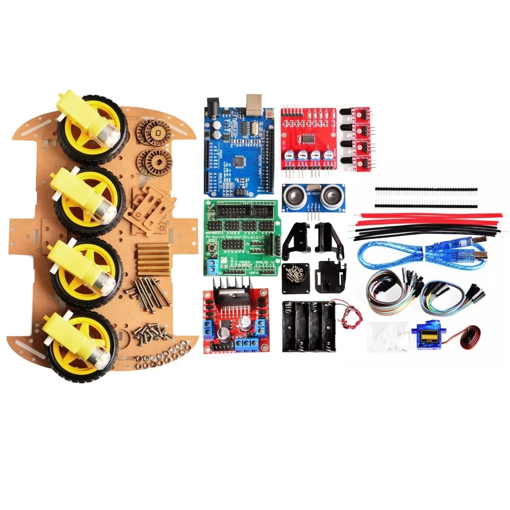
You need two ESP32 DevKit V1 boards, one robot car chassis kit, one L298N module, one PS2 joystick module, and jumper wires. The chassis kit in the parts list includes the frame, TT motors, wheels, a speed encoder, and a battery box. Use the battery box for the motors only, through the L298N, and power the car ESP32 from USB or a separate 5 V source during testing.
Do not power the motors from the ESP32 5 V pin. The TT motors draw far more current than a USB port or a board regulator can supply, and the voltage dips will reset the board. The L298N exists to keep motor current on its own supply. The wiring table below keeps the two supplies separate except for a shared ground.
How do you find the receiver MAC address?
Upload a short sketch to the car board that prints WiFi.macAddress() to the serial monitor at 115200 baud. Set WiFi.mode(WIFI_STA) first, because some cores print zeros before the mode is set. Copy the address from the monitor, for example A4:CF:12:34:56:78, and write it in the sender sketch as {0xA4, 0xCF, 0x12, 0x34, 0x56, 0x78}.
The sender registers that address as a peer with esp_now_add_peer(). The receiver needs no peer entry for a one-way link. It only registers a receive callback with esp_now_register_recv_cb(). The callback signature changed in Arduino core 3.0, so the code below uses a version guard for the receive callback. The sketch as a whole needs core 3.x (target 3.3.13, the stable 3.x release), because analogWrite does not exist in core 2.x. Core 4.0 is not verified for this sketch.
How does the joystick map to motor speed?
The joystick gives two analog readings, one for X and one for Y. Each reading runs 0 to 4095 on the ESP32 12-bit ADC. Center is near 2047. The sender subtracts the center, applies a dead zone of about 200 counts so a resting stick sends zero, and maps the result to a speed range of -255 to 255.
The car mixes speed and turn into left and right speeds. Left speed equals speed plus turn, and right speed equals speed minus turn. Each value is then clamped to -255 to 255. A positive value drives the motor forward, a negative value drives it in reverse, and zero stops it. The L298N direction pins set the direction, and the enable pin PWM sets the speed.
Test the mix on blocks before the car touches the floor. Lift the chassis, run the remote, and watch both wheels. Forward should spin both wheels forward. A right turn should slow or reverse the right wheel. If a wheel runs backward, swap its two motor wires at the L298N output, not in code.
Wiring
Wire the build with the power off. Check every connection in the table before you connect any battery or USB cable.
| From | To | Notes |
|---|---|---|
| Joystick VCC | Remote ESP32 3V3 | 3.3 V logic; the joystick module runs on 3.3 V or 5 V |
| Joystick GND | Remote ESP32 GND | Common ground |
| Joystick VRx | Remote ESP32 GPIO 34 | ADC1 pin; input only, safe with Wi-Fi running |
| Joystick VRy | Remote ESP32 GPIO 35 | ADC1 pin; input only, safe with Wi-Fi running |
| Joystick SW | Remote ESP32 GPIO 32 | Pushbutton; use INPUT_PULLUP and read LOW as pressed |
| Car ESP32 GPIO 25 | L298N ENA | PWM speed, left motor |
| Car ESP32 GPIO 26 | L298N ENB | PWM speed, right motor |
| Car ESP32 GPIO 27, 14 | L298N IN1, IN2 | Left motor direction, 3.3 V logic is enough; L298N reads high from 2.3 V |
| Car ESP32 GPIO 33, 13 | L298N IN3, IN4 | Right motor direction; GPIO 33 is used instead of GPIO 12, which is a flash-voltage strapping pin and must stay low at boot |
| L298N OUT1, OUT2 | Left TT motor | Motor wires; swap here to fix reversed direction |
| L298N OUT3, OUT4 | Right TT motor | Motor wires |
| Battery box positive | L298N 12 V terminal | Motor supply, 6 V from 4 AA cells; keep the 5 V jumper on at 12 V or less |
| Battery box negative | L298N GND and car ESP32 GND | Common ground is required; without it the L298N inputs float |
| USB 5 V | Car ESP32 USB port | Logic supply only; never route motor current through USB |
Power budget
The car has two separate supplies. The motors run from 4 AA cells at about 6 V into the L298N. The L298N drops about 2 V, so each TT motor sees about 4 V. That is normal for this driver and is why a 6 V pack suits 3 to 6 V TT motors.
The car ESP32 runs from USB 5 V during testing. It draws about 80 to 160 mA with the radio on. The L298N logic draws about 40 to 60 mA from the motor supply through its own regulator when the 5 V jumper is fitted. Never feed the motors from the ESP32 5 V pin or from the same USB port that powers the board.
The remote ESP32 runs from USB 5 V. It draws about 80 mA on average, peaking near 240 mA while sending. A small USB power bank works for outdoor driving. Keep the remote and the car on the same ESP-NOW channel, channel 1 in the code below.
Build steps
- Assemble the chassis kit, fit the TT motors and wheels, and mount the L298N and the car ESP32 on the top plate.
- Wire the L298N outputs to the motors and the motor battery to the L298N 12 V terminal. Leave the 5 V jumper on for a 6 V pack.
- Wire the car ESP32 to the L298N control pins from the wiring table. Join the battery negative to the ESP32 ground.
- Upload the MAC print sketch to the car board, read its address from the serial monitor, and write it into the sender sketch.
- Upload the receiver sketch to the car board and the sender sketch to the remote board. Keep the struct identical in both files.
- Wire the joystick to the remote ESP32 from the wiring table. Power the remote from USB.
- Lift the car off the floor, push the stick forward, and confirm both wheels spin forward. Push right and confirm the right wheel slows.
- Set the car on the floor, drive it in a straight line, then walk away until it stops. The 500 ms failsafe should halt it when the link drops.
Code
Libraries: none beyond the ESP32 Arduino core (WiFi.h, esp_now.h and esp_wifi.h ship with the core). Board: ESP32 DevKit V1, Arduino core 3.3.13. analogWrite arrived in core 3.0, so core 2.x will not compile these sketches. Upload the receiver sketch to the car board first, then the sender sketch to the remote board.
// Receiver sketch: ESP-NOW robot car (car board)
// Board: ESP32 DevKit V1. Core: Arduino ESP32 3.x.
#include
#include
#include

// Motor pins on the car board
const int ENA = 25;   // Left motor PWM
const int IN1 = 27;   // Left motor direction A
const int IN2 = 14;   // Left motor direction B
const int ENB = 26;   // Right motor PWM
const int IN3 = 33;   // Right motor direction A (GPIO 12 avoided: strapping pin)
const int IN4 = 13;   // Right motor direction B

// Must match the sender struct exactly, same order and types.
typedef struct {
  int16_t speed;  // -255 to 255, forward is positive
  int16_t turn;   // -255 to 255, right is positive
} DriveCommand;

DriveCommand cmd = {0, 0};
unsigned long lastPacketMs = 0;
const unsigned long FAILSAFE_MS = 500;  // Stop if no packet for 500 ms

void driveMotor(int pwmPin, int inA, int inB, int speed) {
  if (speed >= 0) {
    digitalWrite(inA, HIGH);
    digitalWrite(inB, LOW);
    analogWrite(pwmPin, speed);
  } else {
    digitalWrite(inA, LOW);
    digitalWrite(inB, HIGH);
    analogWrite(pwmPin, -speed);
  }
}

void stopMotors() {
  analogWrite(ENA, 0);
  analogWrite(ENB, 0);
  digitalWrite(IN1, LOW);
  digitalWrite(IN2, LOW);
  digitalWrite(IN3, LOW);
  digitalWrite(IN4, LOW);
}

// Callback signature changed in Arduino core 3.0; this guard covers both.
#if ESP_ARDUINO_VERSION >= ESP_ARDUINO_VERSION_VAL(3, 0, 0)
void onReceive(const esp_now_recv_info_t *info, const uint8_t *data, int len) {
#else
void onReceive(const uint8_t *mac, const uint8_t *data, int len) {
#endif
  if (len == sizeof(cmd)) {
    memcpy(&cmd, data, sizeof(cmd));
    lastPacketMs = millis();
  }
}

void setup() {
  Serial.begin(115200);
  pinMode(ENA, OUTPUT); pinMode(IN1, OUTPUT); pinMode(IN2, OUTPUT);
  pinMode(ENB, OUTPUT); pinMode(IN3, OUTPUT); pinMode(IN4, OUTPUT);
  stopMotors();
  WiFi.mode(WIFI_STA);
  esp_wifi_set_channel(1, WIFI_SECOND_CHAN_NONE);  // Sender must use the same channel
  if (esp_now_init() != ESP_OK) {
    Serial.println("ESP-NOW init failed");
    return;
  }
  esp_now_register_recv_cb(onReceive);
  lastPacketMs = millis();
}

void loop() {
  if (millis() - lastPacketMs > FAILSAFE_MS) {
    stopMotors();  // Link lost: halt the car
    return;
  }
  int left = constrain(cmd.speed + cmd.turn, -255, 255);
  int right = constrain(cmd.speed - cmd.turn, -255, 255);
  driveMotor(ENA, IN1, IN2, left);
  driveMotor(ENB, IN3, IN4, right);
  delay(20);
}

// ---------- Sender sketch: ESP-NOW joystick remote ----------
// Board: ESP32 DevKit V1, Arduino core 3.3.13. Upload to the remote board.
// Replace receiverMac with the MAC address of the car board.
#include
#include
#include

uint8_t receiverMac[] = {0xA4, 0xCF, 0x12, 0x34, 0x56, 0x78};  // Your car board

const int JOY_X = 34;  // ADC1 pin
const int JOY_Y = 35;  // ADC1 pin
const int JOY_SW = 32; // Pushbutton, INPUT_PULLUP

typedef struct {
  int16_t speed;  // Must match the receiver struct exactly
  int16_t turn;
} DriveCommand;

DriveCommand cmd = {0, 0};

int readAxis(int pin) {
  int v = analogRead(pin) - 2047;  // Center is near 2047
  if (v > -200 && v < 200) return 0;  // Dead zone
  return map(constrain(v, -2047, 2047), -2047, 2047, -255, 255);
}

void setup() {
  Serial.begin(115200);
  pinMode(JOY_SW, INPUT_PULLUP);
  WiFi.mode(WIFI_STA);
  esp_wifi_set_channel(1, WIFI_SECOND_CHAN_NONE);  // Receiver must use the same channel
  if (esp_now_init() != ESP_OK) {
    Serial.println("ESP-NOW init failed");
    return;
  }
  esp_now_peer_info_t peer = {};
  memcpy(peer.peer_addr, receiverMac, 6);
  peer.channel = 1;
  peer.encrypt = false;
  if (esp_now_add_peer(&peer) != ESP_OK) {
    Serial.println("Failed to add peer");
  }
}

void loop() {
  cmd.speed = readAxis(JOY_Y);  // Forward is positive
  cmd.turn = readAxis(JOY_X);   // Right is positive
  esp_now_send(receiverMac, (uint8_t *) &cmd, sizeof(cmd));
  delay(50);  // 20 packets per second
}
Test and tune it
Drive the car toward a wall at low speed and release the stick. The car should stop within half a second of the last packet. If it keeps rolling, the failsafe is not running, so check that lastPacketMs updates only inside the receive callback.
If one wheel spins backward, swap that motor's two wires at the L298N output. If the car turns left when you push right, swap the sign of the turn value in the sender, or swap the left and right motor wiring as a pair.
If packets stop arriving beyond a few feet indoors, check that both boards use channel 1 and that the receiver antenna area is clear of the metal chassis plate. Move the car board above the plate if the link is weak.
FAQ
Does ESP-NOW need a router?
No. ESP-NOW sends packets directly from one ESP32 to another by MAC address. It needs no router, no Wi-Fi password, and no internet connection.
What is the ESP-NOW range?
Range is similar to 2.4 GHz Wi-Fi in open air and drops fast through walls. Keep the receiver antenna clear of metal plates and test the failsafe at the edge of range.
Why does my car keep driving after I switch the remote off?
The receiver is not running a link-loss watchdog, or the watchdog timeout is too long. This build stops the motors after 500 ms with no packet. Check that lastPacketMs updates only in the receive callback.
Can I use ESP-NOW with an ESP32-S3 or ESP32-C3 as well?
Yes. ESP-NOW works across the ESP32 family, but the sender and receiver must use the same channel and the same struct. Check the pinout post for your exact board before you wire the L298N.
Why do the motors run slow on a 6 V pack?
The L298N drops about 2 V, so a 6 V pack gives each motor about 4 V. That is normal for this driver. A higher supply is not an option here: the pack is already 6 V and the TT motors are rated 3 to 6 V. Switch to a MOSFET driver such as the TB6612FNG for less drop.
Parts used
Build it with the ESP32 DevKit V1 Development Board, 30-Pin WROOM-32 (two boards, one for the remote and one for the car), the Smart Robot Car Chassis Kit with Speed Encoder and Battery Box for Arduino, 2WD / 4WD, the L298N Dual H-Bridge Motor Driver Module for Arduino, and the HiLetgo Game Joystick Sensor Module, PS2, 2-Axis with Pushbutton. The L298N robot car build in L298N Robot Car: Wire and Drive Two DC Motors covers the same driver in a wired build, and the ESP32 vs ESP32-S3 vs ESP32-C3 vs ESP32-C6 comparison helps if you pick a different board for the remote.
Sources
- Espressif ESP-NOW API reference
- Espressif Arduino-ESP32 documentation
- Espressif ESP32 Series Datasheet
- ST L298 datasheet
Last updated: 2026-11-21. Search volume: not verified. Product links use the store short link form with the product ID; confirm the product slug at publish time.