Which ESP32 Should I Buy? Pick the Right Board for Your Project

Last updated: 2026-11-22

Last updated: 2026-11-22

If you are asking which ESP32 should I buy, start here: buy an ESP32-S3 board. The ESP32-S3 Development Board DevKitC-1 gives dual-core processing at 240 MHz, WiFi, Bluetooth LE, native USB, and enough memory for almost every hobby project. Pick a different chip only for one clear need: Bluetooth audio, a 5 GHz network, a Thread or Matter device, a battery node that must sleep for months, or a large touchscreen.

This guide compares every ESP32 chip Espressif sells, then matches a chip to nine project types: WiFi sensor, camera, battery device, display, robotics, RC, Bluetooth audio, Thread and Matter, and USB HID. Pick the chip first. The board only breaks out the chip pins and adds a USB bridge, a regulator, and buttons.

Table of contents

Which ESP32 should you buy first?

The short answer to which ESP32 should I buy is the ESP32-S3. It is the default pick for 2026 because it covers the most project types: dual-core 240 MHz processing, WiFi, Bluetooth LE 5.0, native USB OTG, a camera interface, and PSRAM options up to 16 MB in the package. It runs Arduino, MicroPython, and ESP-IDF, and most current tutorials target it. Buy the classic ESP32 DevKit V1 instead if you are following an older tutorial word for word: it has the largest pile of existing tutorials and is the only ESP32 chip with Bluetooth Classic. Buy an ESP32-C3 board instead if the node must be tiny, cheap, and low power with only WiFi and Bluetooth LE. Buy an ESP32-C6 board instead if the project joins a Thread, Zigbee, or Matter network.

How do the ESP32 chips compare?

Use this table to pick the chip. GPIO counts are chip totals. A real board breaks out fewer pins, so check the board pinout before you order.

Chip Cores Max clock (MHz) Wi-Fi Bluetooth 802.15.4 USB PSRAM options GPIO on chip
ESP32 2x Xtensa LX6 240 Wi-Fi 4, 2.4 GHz Classic + BLE 4.2 No USB-serial bridge on board, none on chip WROOM none; WROVER 4 or 8 MB 34
ESP32-S2 1x Xtensa LX7 240 Wi-Fi 4, 2.4 GHz None No USB OTG full speed In-package up to 2 MB; external supported 43
ESP32-S3 2x Xtensa LX7 240 Wi-Fi 4, 2.4 GHz BLE 5.0 No USB OTG full speed + USB Serial/JTAG In-package up to 16 MB; external up to 32 MB 45
ESP32-C2 1x RISC-V 120 Wi-Fi 4, 2.4 GHz BLE 5.0 No USB Serial/JTAG only External up to 8 MB; none in package 14
ESP32-C3 1x RISC-V 160 Wi-Fi 4, 2.4 GHz BLE 5.0 No USB Serial/JTAG only External up to 8 MB; none in package 22
ESP32-C5 1x HP RISC-V + 1x LP RISC-V 240 Wi-Fi 6, 2.4 + 5 GHz BLE, Bluetooth Core 6.0 certified Yes, Thread 1.4 + Zigbee 3.0 USB Serial/JTAG only In-package 2 or 8 MB by variant; external up to 32 MB 29
ESP32-C6 1x RISC-V + 1x LP RISC-V 160 Wi-Fi 6, 2.4 GHz BLE 5.3 Yes, Thread + Zigbee USB Serial/JTAG only External up to 16 MB; none in package 30
ESP32-H2 1x RISC-V 96 None BLE 5.3 Yes, Thread + Zigbee USB Serial/JTAG only External up to 16 MB; none in package 19
ESP32-P4 2x RISC-V + 1x LP RISC-V 400 None, needs a companion chip None, needs a companion chip No USB 2.0 high speed OTG + full speed OTG + USB Serial/JTAG In-package 16 or 32 MB 55
ESP32-S31 2x RISC-V + 1x LP RISC-V 320 Wi-Fi 6, 2.4 GHz BLE 5.4 + Classic Yes, Thread 1.4 + Zigbee 3.0 USB OTG high speed In-package 8, 16, or 32 MB 60

On-chip SRAM, per Espressif published data: classic ESP32 520 KB, S2 320 KB, S3 512 KB, C2 272 KB, C3 400 KB, C5 384 KB plus 16 KB low-power SRAM, C6 512 KB, H2 320 KB, P4 768 KB, S31 512 KB. A camera frame, display buffer, or audio buffer that does not fit in SRAM needs PSRAM, and only the S3, C5, P4, and S31 offer it in the package in useful sizes.

Two warnings: the ESP32-P4 has no radio at all, so a P4 board needs a companion chip for WiFi and Bluetooth. The ESP32-S31 datasheet is pre-release v0.6 and the chip was sampling for select customers at last check, so treat the ESP32-S31 as a chip to watch, not a board to buy today.

What does each chip name mean?

The letter after ESP32 names the chip line. S means a high-performance Xtensa chip with USB and, on the ESP32-S3, AI vector instructions. C means a low-cost RISC-V chip. H means a low-power 802.15.4 chip with no WiFi. P means a high-performance RISC-V chip built for screens and video, with no radio. The number is the generation inside the line: the ESP32-S3 is the newer S chip, the ESP32-C6 is the newer C chip with WiFi 6 and 802.15.4, and the ESP32-C5 is the C chip that adds 5 GHz WiFi. Espressif is moving from Xtensa cores to RISC-V cores: the classic ESP32, ESP32-S2, and ESP32-S3 use Xtensa, and every newer chip uses RISC-V. The change does not change how you write Arduino code, because the Arduino-ESP32 core and ESP-IDF support both core types.

Which ESP32 is best for a WiFi sensor?

For a WiFi sensor, the ESP32-C3 is the pick when you ask which ESP32 should I buy. A single RISC-V core at up to 160 MHz reads a sensor and sends the result over WiFi or Bluetooth LE, and the ESP32-C3 runs the lowest deep sleep current in the WiFi group at around 5 uA. Pick the ESP32-C3 SuperMini or the Seeed XIAO ESP32C3 when the node must be small; both carry native USB, so no adapter is needed. Pick the ESP32-C6 for WiFi 6 or a path to Thread, and the classic ESP32 DevKit V1 for an older tutorial. Do not pick the ESP32-S3 for a plain sensor node: it works, but it costs more space and sleep current than the job needs.

Which ESP32 is best for a camera?

The ESP32-S3 is the best pick for a camera. The ESP32-S3-CAM board pairs the ESP32-S3-WROOM-1 N16R8 module, with 16 MB flash and 8 MB PSRAM, with a camera connector, dual USB-C ports, and a TF card slot. The PSRAM holds larger frames, and the ESP32-S3 vector instructions speed up small on-board vision work such as face detection. Compare the two camera boards in ESP32-CAM vs ESP32-S3-CAM: Which Camera Board to Pick, and set the S3 board up with How to Use the ESP32-S3-CAM Board for Camera Projects. Pick the classic ESP32-CAM instead for a simple WiFi camera: a live stream, photos to microSD, and motion alerts, with 4 MB of PSRAM and an OV2640 camera. Do not pick the ESP32-C3 or ESP32-C6 for a camera: neither chip has a camera interface or PSRAM in the package.

Which ESP32 is best for a battery-powered device?

The ESP32-C3 is the best pick for a battery-powered WiFi device, and the ESP32-H2 is the best pick for a battery-powered Thread or Zigbee device. The ESP32-C3 deep sleep current sits around 5 uA, the lowest of the WiFi chips. The ESP32-H2 sits around 7 uA with no WiFi radio to feed. The ESP32-C6 also sits around 7 uA and keeps WiFi 6 plus 802.15.4, so it is the pick when a battery node must talk WiFi today and Thread later. Battery life depends on the board as much as the chip: a board with a power LED, a USB-serial chip, and a linear regulator draws far more than the chip deep sleep figure. Measure the whole board in deep sleep, and read How to Power ESP32 and Arduino Projects on LiPo Power for charging, protection, regulation, and run-time math. Do not pick the ESP32-P4 for a battery device: it is the most power-hungry chip in the family.

Which ESP32 is best for a display?

The ESP32-S3 is the best pick for a display. With PSRAM it drives SPI TFT and OLED displays, holds the frame buffer in memory, and its USB OTG port supports touch input. The 1.9 inch TFT board and the 0.96 inch OLED board are compared pin for pin in ESP32 Boards with Built-In Displays: TFT vs OLED Compared. Pick the ESP32-P4 instead for a large MIPI panel: it drives MIPI-DSI displays up to 1080p, takes MIPI-CSI camera input, and encodes H.264 video in hardware. It has no WiFi or Bluetooth, so a P4 board pairs with a companion chip such as the ESP32-C6 for wireless. Do not pick the ESP32-C3 for a display larger than a small OLED: it has no PSRAM in the package and only 22 GPIO pins on the chip.

Which ESP32 is best for robotics?

The ESP32 DevKit V1 is the best pick for a first robot, and the ESP32-S3 is the best pick for a robot that also needs a camera, a display, or USB. The DevKit V1 gives dual-core 240 MHz processing, WiFi, Bluetooth, 30 pins, and 4 MB of flash on a board that fits a breadboard. The ESP32-S3 adds native USB, more memory, and a camera interface for a vision robot. The robot-by-robot picks, with wiring and power, are in How to Choose ESP32 Boards for Your Robotics Projects. One rule applies to every ESP32 robot: no board pin can power a servo or a motor directly. Every ESP32 runs on 3.3 V logic, so a 5 V sensor needs a level shifter, and servos and motors need their own power supply with a shared ground.

Which ESP32 is best for RC and drones?

The ESP32-C3 SuperMini and the ESP32-S3 SuperMini are the best picks for RC and drones, because size and weight decide the fit. The C3 SuperMini fits tight frames and runs WiFi telemetry, while the S3 SuperMini adds dual-core power and more pins for a flight controller companion or a camera. The ESP32-S2 Mini is the pick for WiFi and USB in a small board without Bluetooth. Drone fitting detail is in How to Choose ESP32 Boards for Drones and FPV Projects, and tiny-board pinouts are in How to Pick an ESP32 SuperMini Board for Tiny Builds. Do not pick the classic ESP32 DevKit V1 for a small drone frame: it is wider than a standard breadboard. Do not pick the ESP32-CAM for a drone that needs pins: the camera and the SD card take most of the free GPIO pins.

Which ESP32 is best for Bluetooth audio?

The classic ESP32 is the only pick for Bluetooth audio. It is the only ESP32 chip with Bluetooth Classic, which is what A2DP audio streaming and the Serial Port Profile (SPP) need. Every newer chip, including the ESP32-S3, ESP32-C3, ESP32-C5, and ESP32-C6, is Bluetooth LE only. Bluetooth LE does not carry A2DP audio, so a Bluetooth speaker or audio receiver must use the classic ESP32. For Bluetooth LE work such as beacons, phone apps, and BLE sensors, any chip with BLE 5 works. The ESP32-S3 is the usual pick, and the ESP32-C3 is the pick when the BLE node must be small and low power.

Which ESP32 is best for Thread, Zigbee, and Matter?

The ESP32-C6 is the best pick for Thread, Zigbee, and Matter. It combines Wi-Fi 6 at 2.4 GHz with an 802.15.4 radio for Thread and Zigbee on one chip, plus Bluetooth LE 5.3, and it supports Matter over Thread and Matter over WiFi. It also carries a low-power RISC-V core that runs while the main core sleeps. Pick the ESP32-H2 instead for a battery-powered Thread or Zigbee end device: same 802.15.4 radio and Bluetooth LE 5.3, no WiFi radio, and the lowest power draw of the two. Pick the ESP32-C5 instead when the Matter device also needs 5 GHz WiFi: it is the only ESP32 chip with dual-band Wi-Fi 6 at 2.4 and 5 GHz, plus 802.15.4. The XIAO family comparison is in XIAO ESP32C3 vs C6 vs S3 vs C5: Pick the Right Board.

Which ESP32 is best for USB HID?

The ESP32-S3 is the best pick for USB HID. It has native USB OTG, so the chip itself can act as a USB keyboard, mouse, MIDI device, or flash drive, with no separate USB chip. The ESP32-S2 also has USB OTG and is the lower-cost pick when the HID device needs WiFi and USB but no Bluetooth. The ESP32-C3, ESP32-C6, ESP32-H2, and ESP32-C5 have USB Serial/JTAG only, a programming and debug port, not a USB device port, so they cannot act as a USB keyboard or mouse. The classic ESP32 has no USB on the chip at all. For USB HID, the choice is the ESP32-S3 first and the ESP32-S2 second.

What about the ESP32-P4?

The ESP32-P4 is a high-performance microcontroller for screens, cameras, and video, not a general ESP32 board. Per the Espressif ESP32-P4 datasheet, it carries a dual-core RISC-V processor at up to 400 MHz, a low-power RISC-V core at up to 40 MHz, 768 KB of SRAM, 16 or 32 MB of PSRAM in the package, 55 GPIO pins, MIPI-CSI camera input, MIPI-DSI display output, an image signal processor, a JPEG codec, and a hardware H.264 encoder, plus USB 2.0 high-speed OTG at 480 Mbps and 10/100 Ethernet. The ESP32-P4 has no WiFi, Bluetooth, or 802.15.4 radio. A P4 board adds wireless with a companion chip, usually the ESP32-C6, over SDIO or SPI. Buy an ESP32-P4 board only for a large touchscreen, a MIPI camera, or hardware video encoding. For every other project, the ESP32-S3 costs less and already has WiFi and Bluetooth on the chip.

What about the ESP32-S31?

The ESP32-S31 is Espressif's newest multi-protocol chip, and it is a chip to watch rather than a board to buy today. Per the Espressif ESP32-S31 product page, it carries a dual-core 32-bit RISC-V processor at up to 320 MHz with a 128-bit SIMD data path, 512 KB of SRAM, 60 GPIO pins, 2.4 GHz Wi-Fi 6, Bluetooth 5.4 with LE and Classic, IEEE 802.15.4 for Thread and Zigbee, a Gigabit Ethernet MAC, USB OTG high speed, and 8, 16, or 32 MB of PSRAM in the package. The ESP32-S31 Series Datasheet is pre-release v0.6, and Espressif described the chip as sampling for select customers when it was announced, so finished boards are scarce and the Arduino and ESP-IDF support is still new, with ESP-IDF v6.1 as the listed target. If you need a board this week, buy the ESP32-S3 or the ESP32-C6 instead.

What about the ESP8266?

The ESP8266 is the predecessor chip, not an ESP32. It gives single-band WiFi on a single core with far fewer pins and no Bluetooth. It still fits one job: a simple WiFi sensor or switch where the board is already in hand and the sketch already works. For a new purchase, the ESP32-C3 costs about the same, adds Bluetooth LE and native USB, and runs the same Arduino code with more pins and more memory. If you already own a NodeMCU ESP8266 board, the setup and OLED guide is in How to Use NodeMCU ESP8266 with a Built-In OLED Display. If you are choosing between Arduino, ESP32, and RP2040, read Arduino vs ESP32 vs RP2040: Which Dev Board for Your Robot first.

Which board, not just which chip?

Once you know which ESP32 should I buy for the chip, pick the board that breaks out the pins you need. The same chip ships on many boards, and the board decides the USB connector, the regulator, the antenna, and the pins you can reach.

Chip Board pick Notes
ESP32 ESP32 DevKit V1, 30-pin, ESP32-WROOM-32 Most tutorials use it
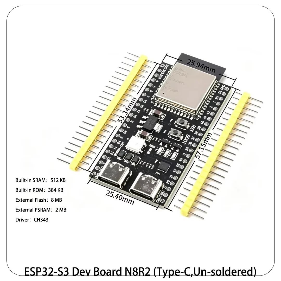
ESP32-S3 ESP32-S3 DevKitC-1, 44-pin, USB-C N16R8 module, 16 MB flash, 8 MB PSRAM
ESP32-S2 ESP32-S2 Mini, USB-C 4 MB flash, 2 MB PSRAM, no Bluetooth
ESP32-C3 ESP32-C3 SuperMini or Seeed XIAO ESP32C3 Thumb-sized, native USB-C
ESP32-C6 ESP32-C6 SuperMini or Seeed XIAO ESP32C6 Wi-Fi 6 and 802.15.4, small board
ESP32-C5 Seeed XIAO ESP32-C5 Dual-band Wi-Fi 6 and Matter
ESP32-H2 ESP32-H2 SuperMini Thread and Zigbee end devices
ESP32-CAM ESP32-CAM with ESP32-CAM-MB carrier Carrier adds Micro USB for programming
ESP32-S3-CAM ESP32-S3-CAM board Dual USB-C, programs directly

Check the board pinout before you order: a 30-pin ESP32 DevKit V1, a 38-pin ESP32-DevKitC, and a 44-pin ESP32-S3 DevKitC-1 do not share a pin layout. The XIAO ESP32S3 and its Sense expansion board are covered in Seeed XIAO ESP32S3 Guide: Standard Board vs Sense Board.

Best for and not for: every chip

These Best for lines are the short answer to which ESP32 should I buy for each chip. Read the project sections above for the reasons.

  • ESP32: Best for older tutorials and Bluetooth Classic audio. Not for Thread, Matter, USB HID, or PSRAM cameras.
  • ESP32-S2: Best for WiFi and USB devices without Bluetooth, such as a USB HID gadget. Not for Bluetooth, Thread, or a camera.
  • ESP32-S3: Best for most buyers, cameras, displays, USB HID, and edge AI. Not for Bluetooth Classic audio, Thread, Matter, or 5 GHz WiFi.
  • ESP32-C2: Best for the lowest-cost simple WiFi node with Bluetooth LE. Not for many pins, PSRAM, or USB OTG.
  • ESP32-C3: Best for tiny low-power WiFi and BLE sensor nodes and battery devices. Not for cameras, large displays, Thread, or USB HID.
  • ESP32-C5: Best for dual-band Wi-Fi 6 with 5 GHz, plus Thread and Matter. Not for USB HID, a camera interface, or the lowest deep sleep current.
  • ESP32-C6: Best for Thread, Zigbee, and Matter devices, and Wi-Fi 6 sensor nodes. Not for cameras, USB HID, or Bluetooth Classic audio.
  • ESP32-H2: Best for battery-powered Thread and Zigbee end devices with Bluetooth LE. Not for WiFi, cameras, displays, or USB HID.
  • ESP32-P4: Best for large MIPI touchscreens, MIPI cameras, and hardware video encoding. Not for WiFi or Bluetooth without a companion chip, and not for battery power.
  • ESP32-S31: Best for watching: WiFi 6, Bluetooth Classic and LE, 802.15.4, Ethernet, and 60 GPIO pins on one chip, once boards ship. Not for buying today: the datasheet is pre-release and the chip was sampling at last check.

What mistakes do first-time buyers make?

First, buying for the chip name instead of the project need. A buyer who needs Thread and buys an ESP32-S3 has bought the wrong chip, because the ESP32-S3 has no 802.15.4 radio. Write down the one radio the project needs before you order. Second, buying a camera board without PSRAM. A camera frame needs memory, and a board without PSRAM holds only small frames. The ESP32-CAM carries 4 MB of PSRAM, and the ESP32-S3-CAM board carries 8 MB. Third, trusting the chip GPIO count instead of the board pinout. The ESP32-S3 chip has 45 GPIO pins, but a board breaks out fewer, and some pins are strapping, flash, or USB pins. Check the board pinout, not the chip datasheet alone. Fourth, assuming every ESP32 board has Bluetooth. The ESP32-S2 has no Bluetooth at all. The ESP32-H2 has no WiFi at all. Read the radio row in the comparison table before you order. Fifth, buying a board with no USB port for programming. The bare ESP32-CAM board has no USB port and needs the ESP32-CAM-MB carrier or an FTDI adapter. The ESP32-S3-CAM board programs directly over dual USB-C ports.

How do you check a new board works?

Run a WiFi scan sketch after the board arrives. The sketch below uses the Arduino-ESP32 core and the built-in WiFi library, so no extra library is needed. It lists the networks the board can see, which proves the radio, the antenna, and the USB connection in one step. Load it in Arduino IDE, open the Serial Monitor at 115200 baud, and check that network names appear.

// Board check: WiFi scan. Arduino-ESP32 core, built-in WiFi library.
// No extra libraries needed. Compiled 2026-11-22 with PlatformIO 6.2.0 (espressif32, esp32dev).
#include <WiFi.h>

void setup() {
  Serial.begin(115200);
  delay(1000);
  WiFi.mode(WIFI_STA);      // Station mode: the board joins networks.
  WiFi.disconnect();        // Clear any saved network before scanning.
  delay(100);
  Serial.println("Scanning for WiFi networks...");
  int networks = WiFi.scanNetworks();
  Serial.print("Networks found: ");
  Serial.println(networks);
  for (int i = 0; i < networks; i++) {
    Serial.print(i + 1);
    Serial.print(": ");
    Serial.print(WiFi.SSID(i));   // Network name.
    Serial.print(" (");
    Serial.print(WiFi.RSSI(i));   // Signal strength in dBm.
    Serial.println(" dBm)");
  }
}

void loop() {
  // Nothing to repeat. Run the scan once per reset.
}

If the scan finds no networks, check the antenna first: some boards ship with a PCB antenna and some with a U.FL connector that needs an antenna fitted. Then check the board selection in Arduino IDE, then the USB cable, because a charge-only cable carries power but no data. The full USB detection fixes are in post 10 in this series.

Frequently asked questions

Which ESP32 should I buy as a beginner?

The ESP32-S3 is the best ESP32 for beginners starting fresh, because it covers WiFi, Bluetooth LE, USB, cameras, and displays on one board. The classic ESP32 DevKit V1 is the best ESP32 for beginners following an older tutorial, because most older tutorials name the classic ESP32 pins. Either board runs the Arduino-ESP32 core.

What is the difference between ESP32 and ESP32-S3?

The ESP32 is the classic dual-core Xtensa LX6 chip at 240 MHz with Wi-Fi 4, Bluetooth Classic and BLE 4.2, and 34 GPIO pins. The ESP32-S3 is the newer dual-core Xtensa LX7 chip at 240 MHz with Wi-Fi 4, Bluetooth LE 5.0, native USB OTG, a camera interface, AI vector instructions, and 45 GPIO pins. The ESP32-S3 has no Bluetooth Classic and no 802.15.4 radio.

Which ESP32 has the most GPIO pins?

The ESP32-S31 has the most GPIO pins at 60 on the chip, per the Espressif ESP32-S31 datasheet, but the chip was sampling at last check. Among boards you can buy today, the ESP32-P4 has 55 and the ESP32-S3 has 45. A board breaks out fewer pins than the chip total, so check the board pinout.

Does the ESP32-C6 support Matter?

Yes. The ESP32-C6 supports Matter over Thread and Matter over WiFi, per Espressif, combining Wi-Fi 6 at 2.4 GHz with an 802.15.4 radio for Thread and Zigbee and Bluetooth LE 5.3. The ESP32-H2 also supports Matter over Thread, and the ESP32-C5 adds 5 GHz WiFi to the same Matter support.

Which ESP32 should I buy for a battery project?

The ESP32-C3 is the best ESP32 for a battery-powered WiFi project, with deep sleep current around 5 uA. The ESP32-H2 is the best ESP32 for a battery-powered Thread or Zigbee project, with no WiFi radio to feed. Read How to Power ESP32 and Arduino Projects on LiPo Power for the charging, protection, and run-time math: the board draws more than the chip deep sleep figure.

Parts used in this guide

If you already know which ESP32 should I buy for your project, the boards below are in stock in the store and linked to their product pages. Use the product page for the current listing. Product images in the body link to their products.

In this series

This pillar is post 1 of 10. The spoke posts below come next in this series. Their links are added here when each post publishes.

  • Post 2: ESP32 DevKit V1 (30-pin) pinout.
  • Post 3: ESP32-S3 DevKitC-1 pinout.
  • Post 4: ESP32-CAM pinout, boot mode, and flashing.
  • Post 5: ESP32-CAM troubleshooting.
  • Post 6: ESP32-CAM streaming.
  • Post 7: ESP32-CAM on battery.
  • Post 8: ESP-NOW explained.
  • Post 9: Arduino IDE vs PlatformIO vs ESP-IDF vs MicroPython for ESP32.
  • Post 10: ESP32 not detected over USB.

Sources

  • Espressif ESP32-S31 product page: dual-core 32-bit RISC-V up to 320 MHz, 512 KB SRAM, 60 GPIO pins, Wi-Fi 6, Bluetooth 5.4 LE and Classic, 802.15.4, Gigabit Ethernet, USB OTG high speed, 8 to 32 MB PSRAM. https://www.espressif.com/en/products/socs/esp32-s31
  • ESP32-S31 Series Datasheet, pre-release v0.6: HP dual-core RISC-V up to 320 MHz, LP core up to 40 MHz, 60 GPIO pins, Wi-Fi 6, Bluetooth 5.4, Zigbee 3.0, Thread 1.4. https://documentation.espressif.com/esp32-s31_datasheet_en.html
  • ESP32-P4 Series Datasheet, pre-release v0.7: dual-core RISC-V up to 400 MHz, 768 KB SRAM, 16 or 32 MB PSRAM, 55 GPIO pins, MIPI-CSI and MIPI-DSI, H.264 encoder, USB 2.0 high-speed OTG, no radio. https://documentation.espressif.com/esp32-p4_datasheet_en.html
  • Zephyr Project, ESP32-C5 features: HP RISC-V core up to 240 MHz, 384 KB SRAM, dual-band Wi-Fi 6, Bluetooth 5.4 LE, 802.15.4, 29 GPIO pins. https://docs.zephyrproject.org/latest/boards/espressif/common/soc-esp32c5-features.html
  • Espressif ESP32-C5 datasheet (mirror of the Espressif PDF): HP RISC-V core up to 240 MHz, LP core up to 40 or 48 MHz, 384 KB HP SRAM, 16 KB LP SRAM, Bluetooth Core 6.0 certified, Thread 1.4, Zigbee 3.0, 29 GPIO pins. https://www.alldatasheet.com/datasheet-pdf/pdf/2162612/ESPRESSIF/ESP32-C5.html
  • Espressif series datasheets for ESP32, ESP32-S2, ESP32-S3, ESP32-C3, ESP32-C6, and ESP32-H2: cores, clocks, radios, SRAM, GPIO counts, and USB support in the comparison table, cross-checked against the Espressif data quoted in the JLCPCB ESP32 versions guide, the Blynk ESP32 variant guide, and the esp32.iammanis.com specifications table.
LVGL ESP32 Display Guide: Setup, Widgets, Touch

LVGL turns a plain TFT display into a real interface. With TFT_eSPI alone, your code draws pixels, lines, and text by hand. With LVGL on top, you get buttons, sliders, gauges, menus, and touch input.

Short answer: install the LVGL 9 library in the Arduino IDE, set up TFT_eSPI for your display driver, connect the two with a flush callback or the LVGL TFT_eSPI helper, then build your screen from widgets. The worked example uses the 2.4 inch touch ILI9341 module from the store. This draft is written against LVGL 9.x, verified against the LVGL docs and the Random Nerd Tutorials LVGL 9.2 example.

What is LVGL, and when should you use it instead of TFT_eSPI alone?

LVGL stands for Light and Versatile Graphics Library. It is a free and open-source graphics library for microcontrollers, released under the MIT license. It gives you widgets (buttons, labels, sliders, charts, lists, images), layout management, event handling, animations, CSS-like styling, multi-language support with UTF-8, and support for touchpads, mice, keyboards, and encoders. It is written in C. Source: LVGL docs and Random Nerd Tutorials.

LVGL does not drive your display. LVGL renders your interface into a memory buffer, then calls a function you provide, the flush callback, to move those pixels to the screen. The display driver, usually TFT_eSPI on an ESP32 SPI display, does the actual SPI transfer.

Use TFT_eSPI alone when the screen shows fixed text, a simple readout, or a static gauge. Use LVGL when the screen needs buttons, menus, sliders, or screens the user navigates. If you have not installed TFT_eSPI yet, follow our TFT_eSPI setup guide first.

Which LVGL version is this guide written against?

This guide is written against LVGL 9.x. The worked Arduino example follows the Random Nerd Tutorials guide, which installs LVGL version 9.2 from the Arduino Library Manager. The LVGL documentation site currently serves the 9.4 docs.

Item LVGL 8.x LVGL 9.x (this guide)
Display driver lv_disp_drv_t, lv_disp_drv_register lv_display_t, lv_display_create
Draw buffer lv_disp_draw_buf_t Buffers passed to lv_display_create
Flush ready call lv_disp_flush_ready lv_display_flush_ready
Input device lv_indev_drv_t, lv_indev_drv_register lv_indev_t, lv_indev_create
Active screen lv_scr_act() lv_screen_active()
Button create lv_btn_create lv_button_create
Main loop call lv_task_handler lv_timer_handler

Source: LVGL 9 docs and the ElectricalFlux LVGL ESP32-S3 guide.

What do you need before you start?

  • An ESP32 board. This guide uses the ESP32 DevKit V1, the same board as the TFT_eSPI setup guide, because its hardware SPI pins match the library examples.
  • A separate SPI TFT module. The worked examples use the 2.4 inch touch ILI9341 module and the 0.96 inch ST7735 module from the store.
  • The Arduino IDE with the ESP32 board package installed, version 2.x or later.
  • TFT_eSPI installed and configured for your display, per our TFT_eSPI setup guide. A setup that already passes its Colour_Test sketch is the starting point.
  • Jumper wires and a breadboard. Keep the SPI wires short: long wires cause signal problems at full SPI speed.

How do you install LVGL in the Arduino IDE?

Open the Library Manager: Sketch, Include Library, Manage Libraries. Search for “lvgl”, find the entry by kisvegabor, and install version 9.2 or later in the 9.x line. Do not install a version 8 release alongside it: one LVGL version per project, and the code in this guide is written for 9.x.

Then prepare the LVGL config file, lv_conf.h. LVGL ships with a template file, lv_conf_template.h, inside the library folder. Copy it, rename the copy to lv_conf.h, and place it in your Arduino libraries folder, not inside the lvgl folder.

Open lv_conf.h and check two settings: the guard near the top that disables the whole file when it is set to 0 must be set to 1, and color depth LV_COLOR_DEPTH must be 16 (RGB565, the 16-bit color TFT_eSPI sends to the display). Your sketch starts with two lines that tell LVGL to use this config file:

#define LV_CONF_INCLUDE_SIMPLE
#include <lvgl.h>

Source: Random Nerd Tutorials LVGL 9.2 guide and the CircuitDigest LVGL Arduino tutorial. If the sketch fails to compile with errors about lv_conf.h not found, the file is in the wrong folder.

How do you wire the display?

Use the same wiring as the TFT_eSPI setup guide. LVGL does not change the wiring: TFT_eSPI still owns the SPI bus, and LVGL only hands it pixels. For an ESP32 DevKit V1 the display wires to the hardware SPI pins: MOSI 23, MISO 19, SCLK 18, CS 15, DC 2, RST 4, with VCC at 3.3V and BLK at 3V3 or a free GPIO for dimming. Connect MISO even if you think you do not need it: the display ID read and the touch controller need it. The full wiring table and the User_Setup.h edit for each driver are in our TFT_eSPI setup guide.

Which display drivers does LVGL work with?

LVGL works with any display driver that can move a rectangle of pixels to the screen. For the store TFT modules, the driver is TFT_eSPI: it supports the ST7735, ST7789, ILI9341, ILI9488, and ST7796 chips, per the TFT_eSPI README. The GC9A01 round display needs its own low-level driver code, as in the CircuitDigest LVGL tutorial. The built-in 1.9 inch ST7789 board (ID 17819) works the same way: TFT_eSPI with the ST7789 driver at 170 by 320, CS 5, RST 4, BL 32, and MOSI 23.

How do you bind LVGL to your display driver?

Binding means telling LVGL three things: how big the screen is, where to put rendered pixels while they wait, and which function moves them to the display. Route A is the one to use with TFT_eSPI. Route B is the manual route, for other display drivers.

Route A: the TFT_eSPI helper (use this first)

LVGL 9 ships a helper that binds TFT_eSPI in one call. The Random Nerd Tutorials LVGL 9.2 example uses it, and it needs no flush callback of your own:

#define SCREEN_WIDTH 240
#define SCREEN_HEIGHT 320

#define DRAW_BUF_SIZE (SCREEN_WIDTH * SCREEN_HEIGHT / 10 * (LV_COLOR_DEPTH / 8))
uint32_t draw_buf[DRAW_BUF_SIZE / 4];

void setup() {
  Serial.begin(115200);
  lv_init();
  lv_display_t * disp;
  disp = lv_tft_espi_create(SCREEN_WIDTH, SCREEN_HEIGHT, draw_buf, sizeof(draw_buf));
  lv_display_set_rotation(disp, LV_DISPLAY_ROTATION_270);
}

lv_tft_espi_create creates the LVGL display, registers the TFT_eSPI flush function behind the scenes, and attaches your draw buffer. The rotation call turns the portrait 240 by 320 panel into landscape. Source: Random Nerd Tutorials.

DRAW_BUF_SIZE is one tenth of the screen, in 16-bit pixels: 7,680 pixels, or 15,360 bytes, for a 240 by 320 screen. A bigger buffer means smoother animation but costs RAM. If animations stutter, raise it to one quarter. If the sketch crashes on boot, shrink it.

Route B: the manual flush callback

If your display driver is not TFT_eSPI, write the flush callback yourself. LVGL calls it whenever a rectangle of the screen needs updating. The callback receives the display, the rectangle (area), and the pixel data (px_map), sends that rectangle to the screen, then tells LVGL the buffer is free:

void my_disp_flush(lv_display_t *disp, const lv_area_t *area, uint8_t *px_map)
{
  uint32_t w = (area->x2 - area->x1 + 1);
  uint32_t h = (area->y2 - area->y1 + 1);
  lcd.startWrite();
  lcd.setAddrWindow(area->x1, area->y1, w, h);
  lcd.pushColors((uint16_t *)px_map, w * h, true);
  lcd.endWrite();
  lv_display_flush_ready(disp);
}

The area coordinates are inclusive, so both dimensions need plus 1. lv_display_flush_ready(disp) is not optional: without it, LVGL waits forever for a buffer that never comes back, and the screen freezes after the first frame. Register the callback with lv_display_create, lv_display_set_buffers, and lv_display_set_flush_cb. Source: SmartDocs. Two buffers give double buffering; one buffer works too and uses half the RAM.

How do you build the first screen?

Once the display is bound, the rest is widgets. This example is adapted from the Random Nerd Tutorials LVGL 9.2 sketch: a label, a button that counts clicks, and a slider that prints its value.

void lv_create_main_gui(void) {
  lv_obj_t * text_label = lv_label_create(lv_screen_active());
  lv_label_set_text(text_label, "Hello, world!");
  lv_obj_align(text_label, LV_ALIGN_CENTER, 0, -90);

  lv_obj_t * btn1 = lv_button_create(lv_screen_active());
  lv_obj_add_event_cb(btn1, event_handler_btn1, LV_EVENT_ALL, NULL);
  lv_obj_align(btn1, LV_ALIGN_CENTER, 0, -50);
  lv_obj_t * btn_label = lv_label_create(btn1);
  lv_label_set_text(btn_label, "Button");
  lv_obj_center(btn_label);

  lv_obj_t * slider = lv_slider_create(lv_screen_active());
  lv_obj_align(slider, LV_ALIGN_CENTER, 0, 60);
  lv_obj_add_event_cb(slider, slider_event_callback, LV_EVENT_VALUE_CHANGED, NULL);
  lv_slider_set_range(slider, 0, 100);
}

The event callback reads the event code and acts on it:

static void event_handler_btn1(lv_event_t * e) {
  lv_event_code_t code = lv_event_get_code(e);
  if(code == LV_EVENT_CLICKED) {
    btn1_count++;
  }
}

And the main loop hands time to LVGL. LVGL needs a millisecond tick and regular calls to its handler, or nothing moves: no animations, no touch, no screen updates.

void loop() {
  lv_timer_handler();
  lv_tick_inc(5);
  delay(5);
}

Source: Random Nerd Tutorials. Note that their code calls the handler lv_task_handler, the LVGL 8 name. In LVGL 9 the function is lv_timer_handler. If your loop blocks for more than a few milliseconds, the interface freezes for the same time.

Which widgets should you use?

Every widget follows the same pattern: create it on a parent, set its size and position, style it, and add an event callback if it takes input.

Widget Create call (LVGL 9) Use it for
Label lv_label_create Text, readouts, titles
Button lv_button_create Actions, toggles, navigation
Slider lv_slider_create Brightness, volume, setpoints from 0 to 100
Bar lv_bar_create Progress, battery level, signal strength

LVGL also has arcs, charts, images, dropdowns, switches, keyboards, text areas, menus, tabs, tables, and animations; the full list is in the LVGL docs widget section. Two rules apply to all of them. First, every object has a parent: a widget created with no parent goes on the active screen, and a widget created on a button becomes part of that button, like the label inside btn1 above. Second, styles are CSS-like: set colors, fonts, padding, and radius per widget, or per state, such as pressed or checked. Source: Random Nerd Tutorials and the LVGL docs widget examples.

How do you add touch input?

A touch display needs a second driver: one for the screen, one for the touch controller. The touch modules in the store use the XPT2046 resistive touch controller. The steps below follow the Random Nerd Tutorials LVGL 9.2 example.

Install the XPT2046_Touchscreen library from the Library Manager, then define the touch pins and start a second SPI bus for the touch chip. The touch chip has its own chip select, so it shares MOSI, MISO, and SCK with the display:

#define XPT2046_IRQ 36
#define XPT2046_MOSI 32
#define XPT2046_MISO 39
#define XPT2046_CLK 25
#define XPT2046_CS 33

SPIClass touchscreenSPI = SPIClass(VSPI);
XPT2046_Touchscreen touchscreen(XPT2046_CS, XPT2046_IRQ);

In setup, start the touch SPI, begin the touchscreen, and set its rotation to match the display rotation. Then register the touch input device with LVGL and give it a read callback:

touchscreenSPI.begin(XPT2046_CLK, XPT2046_MISO, XPT2046_MOSI, XPT2046_CS);
touchscreen.begin(touchscreenSPI);
touchscreen.setRotation(2);

lv_indev_t * indev = lv_indev_create();
lv_indev_set_type(indev, LV_INDEV_TYPE_POINTER);
lv_indev_set_read_cb(indev, touchscreen_read);

The read callback checks the touch state, reads the point, and maps the raw touch values to screen pixels:

void touchscreen_read(lv_indev_t * indev, lv_indev_data_t * data) {
  if(touchscreen.tirqTouched() && touchscreen.touched()) {
    TS_Point p = touchscreen.getPoint();
    x = map(p.x, 200, 3700, 1, SCREEN_WIDTH);
    y = map(p.y, 240, 3800, 1, SCREEN_HEIGHT);
    data->state = LV_INDEV_STATE_PRESSED;
    data->point.x = x;
    data->point.y = y;
  }
  else {
    data->state = LV_INDEV_STATE_RELEASED;
  }
}

Source: Random Nerd Tutorials. Two warnings. First, the calibration numbers in the map calls, 200 to 3700 on X and 240 to 3800 on Y, are the values for the 2.8 inch touch module in that tutorial, not the 2.4 inch touch module in the store. Read the raw touch values from your own module, then set the map limits to your module. A button that only responds on one side of the screen is almost always a calibration problem. Second, if the touch picture is upside down or mirrored, change the touchscreen rotation value, not the LVGL rotation.

How do you use fonts and images?

LVGL ships with built-in fonts, and it can load custom fonts and images.

Built-in fonts. LVGL includes the Montserrat font in several sizes, enabled in lv_conf.h. A label uses the default font unless you set another one with lv_obj_set_style_text_font. Keep the enabled set small: every font size adds flash use.

Custom fonts. For a font LVGL does not ship, use the LVGL font converter linked from the LVGL docs. It converts a font file into a C array you add to your sketch. Generate it for LVGL 9, not LVGL 8.

Images. LVGL shows images from C arrays compiled into the sketch, or from files on a filesystem such as an SD card. The LVGL image converter, also linked from the LVGL docs, turns a PNG or JPG into a C array. A full-screen photo at 240 by 320 in 16-bit color is about 150 kB, so keep images small or load them from a card.

What about the ESP-IDF path?

The Arduino path above is the fastest way to a working screen. The ESP-IDF path gives more control, and it is the path Espressif documents for production firmware. The LVGL docs page “Add LVGL to an ESP32 IDF project” covers it.

The simplest ESP-IDF route is the esp_lvgl_port component, which provides helper functions for installing LVGL and display drivers, plus touch, encoder, button, and USB HID input support:

idf.py create-project my_lvgl_app
cd my_lvgl_app
idf.py add-dependency "espressif/esp_lvgl_port^2.3.0"

The esp_lvgl_port component supports LVGL versions 8 and 9 and is compatible with ESP-IDF v5.2 and above. By default it pulls the latest stable LVGL, so pin a version if your project must stay on one. To add LVGL without the port component, use idf.py add-dependency “lvgl/lvgl^9.*”. Then configure LVGL with idf.py menuconfig and add a display driver and a touch driver from the ESP component registry. Source: LVGL docs, “Add LVGL to an ESP32 IDF project”.

What are the common mistakes?

  • Mixing LVGL 8 code with LVGL 9. lv_disp_drv_t, lv_btn_create, lv_scr_act, and lv_task_handler are LVGL 8 names. LVGL 9 uses lv_display_t, lv_button_create, lv_screen_active, and lv_timer_handler. One version per project.
  • A lv_conf.h from another tutorial. The config file must match your LVGL version and your display. Copy the template from your own installed library.
  • Forgetting lv_display_flush_ready in a manual flush callback. The screen draws one frame, then freezes forever.
  • No tick and no handler in loop. LVGL needs lv_tick_inc and lv_timer_handler called regularly. A blocking loop freezes the interface.
  • A draw buffer that is too small or too big. Too small and animations stutter. Too big and the sketch crashes on boot. Start at one tenth of the screen, and set LV_COLOR_DEPTH to 16: the store TFT modules use 16-bit color.

How do you fix an LVGL display that does not work?

Work through the stack from the bottom up: wiring, TFT_eSPI, LVGL config, then your code.

The screen stays white or black after upload. Check the backlight first, then run Colour_Test without LVGL. If Colour_Test fails, the problem is wiring or User_Setup.h, not LVGL. Source: our TFT_eSPI setup guide.

The screen shows the first frame, then freezes. The flush callback never told LVGL the buffer was free. Check that lv_display_flush_ready(disp) runs at the end of your flush callback.

The picture is there but the colors are wrong. Check LV_COLOR_DEPTH is 16, and check the byte swap setting in TFT_eSPI. The SmartDocs guide lists enabling byte swapping with tft.setSwapBytes(true) as the fix for garbled colors. Source: SmartDocs.

Buttons do not respond to touch. Check lv_indev_create and lv_indev_set_read_cb ran in setup, check the touch CS pin, and check the calibration map limits. Source: SmartDocs and Random Nerd Tutorials.

Which route should you pick?

Match the tool to the job. For display selection, see our display buying guide.

Project Pick Why
Temperature readout, clock, status text TFT_eSPI alone No buttons, no menus, less code
Thermostat with setpoint buttons LVGL on TFT_eSPI, Route A Buttons and a slider, one afternoon of work
Production firmware LVGL on ESP-IDF with esp_lvgl_port Version-pinned components and full control

Parts used in this guide

Prices and stock were verified live on qualityrcparts.com on 2026-11-21 through the public Store API. All four items are in stock.

Shipped fast and securely from our secure facility in Queensbury, NY. QRC ships within the USA only.

Related guides

FAQ

What is LVGL? LVGL is the Light and Versatile Graphics Library, a free and open-source graphics library under the MIT license. It provides widgets such as buttons, labels, sliders, charts, and lists, plus layouts, styles, animations, and touch input. Source: LVGL docs and Random Nerd Tutorials.

Can I use LVGL with an ESP32 and a TFT display? Yes. Install LVGL 9 in the Arduino IDE, set up TFT_eSPI for your display driver, bind them with the TFT_eSPI helper or a flush callback, then build your screen from widgets. Source: Random Nerd Tutorials LVGL 9.2 guide.

Which LVGL version should I install? Install LVGL 9.x for a new project. This guide is written against LVGL 9.2, and the LVGL docs currently serve the 9.4 line. LVGL 9 changed the display, input device, button, and screen function names, so LVGL 8 code will not compile against LVGL 9 without changes. Source: LVGL docs and the ElectricalFlux LVGL ESP32-S3 guide.

Why is my LVGL screen blank after upload? Check the backlight first, then run the TFT_eSPI Colour_Test sketch without LVGL. If Colour_Test fails, the problem is wiring or User_Setup.h, not LVGL. If it passes, check lv_conf.h placement and that loop calls lv_timer_handler and lv_tick_inc. Source: our TFT_eSPI setup guide and SmartDocs.

How do I add touch to LVGL on ESP32? Use the XPT2046 touch controller on touch TFT modules. Install the XPT2046_Touchscreen library, start a second SPI bus for the touch chip with its own chip select pin, register an LVGL input device with lv_indev_create, and set a read callback that maps raw touch values to screen pixels. Source: Random Nerd Tutorials.

Can I use LVGL with ESP-IDF instead of Arduino? Yes. Add the esp_lvgl_port component with idf.py add-dependency “espressif/esp_lvgl_port^2.3.0”, or add LVGL directly with idf.py add-dependency “lvgl/lvgl^9.*”. Source: LVGL docs, “Add LVGL to an ESP32 IDF project”.

Sources

Last updated: 2026-11-21

Low-Power ESP32 Battery Projects: Deep Sleep and Solar

A battery ESP32 project lives or dies on one number: average current. Get it right and a single 3000 mAh cell runs a field sensor for months. Get it wrong and the same cell is dead before dinner.

This guide covers the five power modes, every wake source, board-level sleep drain, battery sizing, solar sizing, and the mistakes that drain a pack in days. The sensor node build is covered in ESP32 Battery Sensor Node: Deep Sleep and Power Budget, and LiPo wiring in How to Power ESP32 and Arduino Projects on LiPo Power.

How long can an ESP32 really run on battery?

Battery life in hours equals usable battery capacity divided by average current. Average current is the awake share times the awake current, plus the sleep share times the sleep current. Source: ProjectECH; DroneBot Workshop; Hubble.

Take a node that wakes for 20 seconds at 180 mA and sleeps at 15 microamps, on one 18650 cell with a realistic usable capacity of 2400 mAh. Source: ProjectECH.

Report interval Average current Battery life from 2400 mAh
Every 10 minutes (180 x 20 + 0.015 x 580) / 600 = about 6.0 mA About 400 hours, about 16 days
Every 60 minutes (180 x 20 + 0.015 x 3580) / 3600 = about 1.01 mA About 2376 hours, about 99 days

Three lessons fall out of that table. First, the interval dominates: 60-minute reports give roughly 6 times the battery life of 10-minute reports. Second, sleep current matters: with a 5 mA sleep the 60-minute column collapses to about 17 days. Third, awake time is the other lever: Wi-Fi can spend 3 to 8 seconds just joining the network, so cut the awake window to 5 seconds. Source: ProjectECH.

Radios differ too: Wi-Fi transmit runs about 160 to 260 mA, BLE about 95 to 130 mA, and LoRa about 20 to 120 mA transmit with about 0.2 microamps in sleep. Source: ProjectECH; Hubble.

Which sleep mode does your project need?

The ESP32 has five power states. The figures below are chip-level typicals; your board will draw more. Source: DroneBot Workshop; Espressif sleep modes documentation.

Mode CPU and peripherals Radio Typical chip current What survives
Active On On or off 240 mA Wi-Fi transmit peak Everything
Modem sleep On Off between checks About 3 to 20 mA Everything, Wi-Fi association kept
Light sleep Paused Off About 0.8 mA RAM and registers, resumes where it stopped
Deep sleep Off Off About 10 to 25 microamps RTC memory only, 8 KB slow memory
Hibernation Off Off About 2.5 microamps Nothing guaranteed, not even RTC memory

Active is the normal running state; the only saving is lowering the CPU clock. Modem sleep turns the radios off between transmissions while the CPU keeps running, staying associated with the router by waking the radio on the DTIM interval. Light sleep pauses the CPU clock but preserves RAM and registers. Deep sleep powers down almost everything; only the RTC domain and optionally the ULP coprocessor stay alive. Hibernation is the deepest state: even the 8 MHz RTC oscillator and the ULP coprocessor are off, and RTC memory is not guaranteed. The only wake source is an EXT0 GPIO interrupt. Source: DroneBot Workshop.

What wakes the ESP32 from deep sleep?

The wake source defines the whole power profile. Source: ProjectECH; DroneBot Workshop; Hubble.

Wake source How it works Best for
Timer wake RTC timer fires after N microseconds Periodic sensing: wake, read, send, sleep
EXT0 wake One RTC GPIO goes high or low One event: a PIR motion sensor, a float switch, a door switch
EXT1 wake Any of several RTC GPIOs changes Several events at once
Touch pad wake A configured touch pad crosses its threshold A manual “report now” button on a sealed enclosure
ULP coprocessor Runs while the main CPUs sleep, about 150 microamps typical Wake the main CPU only on a threshold

Timer wake is the workhorse: call esp_sleep_enable_timer_wakeup(), then esp_deep_sleep_start(). EXT0 and EXT1 wake on a pin: EXT0 watches one RTC GPIO at one level, ideal for a PIR sensor, and EXT1 watches several. On the standard ESP32, RTC-capable GPIOs are 0, 2, 4, 12 to 15, 25 to 27, and 32 to 39. Touch wake uses the capacitive touch pins. The ULP coprocessor can poll an ADC channel or a GPIO while the main CPUs sleep and wake the main CPU only on a threshold. Source: ProjectECH; DroneBot Workshop; Hubble.

Always configure a wake source first, or the chip sleeps forever. Source: ProjectECH.

State survives deep sleep through RTC slow memory: variables declared with RTC_DATA_ATTR survive deep sleep, but not a power loss or a hard reset. Source: ProjectECH; TheLinuxCode; post 23387.

Why does your dev board never reach the datasheet sleep current?

The datasheet deep sleep figure is the bare chip. A dev board adds parts that draw current around the clock, and those parts dominate the sleep budget. Source: ProjectECH; DroneBot Workshop; post 23387.

A typical 30-pin DevKit board carries an AMS1117-3.3 linear regulator with a quiescent current of about 5 mA typical. With the USB chip, power LED, and pull-ups added, a “sleeping” dev board typically draws 5 to 15 mA. At 10 mA, a 3000 mAh cell lasts 300 hours, under two weeks. Source: ProjectECH; DroneBot Workshop.

Fix it in one of three ways: power the board through the 3V3 pin from an efficient external regulator; use a bare ESP32 module on a minimal breakout; or use a board designed for battery use. Measure the sleep current yourself first. Source: ProjectECH.

The XIAO boards stocked at QRC are the battery-friendly end of this scale, and the figures conflict across sources, so they are stated here as a sourced range, never as a single bench-tested number. Seeed’s wiki lists the plain XIAO ESP32S3 at 14 microamps in deep sleep, 2 mA in light sleep, and 27 mA in modem sleep. The XIAO ESP32S3 Sense with its expansion board attached is listed at 3 mA in deep sleep: the expansion board costs roughly 200 times the plain board’s sleep current, so detach it for a battery build and use the detachable camera only when the project needs it. The XIAO ESP32S3 Plus is listed at 33.51 microamps in deep sleep, and the XIAO ESP32C3 at 44 microamps. CircuitDigest measured a plain XIAO ESP32S3 board at 130 microamps in deep sleep, against a bare ESP32-S3 chip rating of 7 to 8 microamps. Plan with the worst figure in the range. Source: Seeed Studio XIAO ESP32S3 wiki; CircuitDigest; Embedded Nerd.

How do you size the battery?

Measure the build that will actually run from the battery. Source: UMA Technology; Hubble.

Step 1: measure each operating state. Record current in each state with a USB power meter, and use a multimeter in series with the battery lead for sleep. Source: UMA Technology; Hubble.

Step 2: calculate the average current. For each state, multiply current by time in that state, then sum and divide by the cycle time. Example: wake every 15 minutes, transmit for 5 seconds at 150 mA, sleep the other 895 seconds at 15 microamps. Average equals (5 x 150 + 895 x 0.015) / 900, which is 0.85 mA. Source: Hubble.

Step 3: divide capacity by average current, then derate. A 3000 mAh battery at 0.85 mA average gives about 3,500 hours, about 146 days. Now derate: usable capacity is about 70 to 80 percent of the label after aging, temperature, and self-discharge, so plan on about 2400 mAh usable from a 3000 mAh cell. Source: ProjectECH; Hubble; e-fm.tech.

Step 4: pick the chemistry. A standard LiPo at 3.7 V is workable for 6 to 12 month projects. A LiFePO4 cell at 3.2 V has low self-discharge around 3 percent per year, so it suits solar recharging. A CR2032 at 220 mAh suits only the lowest-power applications. Source: Hubble.

The biggest lever is the awake time: every second of Wi-Fi connect time at 150 mA costs as much as 150 seconds of sleep at 1 mA. Source: post 23387.

How do you size a solar panel for an ESP32 project?

A solar panel only has to replace what the board uses, plus the charging losses. Size it from the worst month, not the average: a panel sized for summer sun dies by mid-December. Source: Hubble solar sizing guide; e-fm.tech.

Step 1: daily energy. Daily energy equals average current times supply voltage times 24 hours. The 0.85 mA node at 3.7 V uses about 76 mWh per day. Source: Hubble solar sizing guide.

Step 2: battery autonomy. Size for three cloudy days: three days at 76 mWh per day is 228 mWh, or about 62 mAh at 3.7 V. Source: e-fm.tech; post 23188; post 15185.

Step 3: worst-month peak sun hours. Peak sun hours are the hours per day of full sunlight that would deliver the same energy as the real day. Look it up for your coordinates with PVGIS or NASA POWER, and use the worst month. Source: e-fm.tech.

Step 4: panel watts. Panel watts are about equal to daily energy divided by (charging efficiency times peak sun hours times a derating factor). The worked example comes out to about 0.021 to 0.11 W. In practice, fit a panel several times larger than the paper minimum. Source: e-fm.tech; Hubble solar sizing guide.

Step 5: charge controller. A small panel charging a single lithium cell needs a charger that terminates at 4.2 V and a protection circuit. The TP4056 module below charges a single cell from USB or a solar panel at up to 1 A. Standard lithium-ion and LiPo cells should not be charged below about 0 degrees C. Source: ProjectECH; e-fm.tech.

No solar panel is stocked at QRC as of 2026-11-21, so no panel is linked in this guide. The BirdBox build in Run a BirdBox Camera for Months on Solar Power shows the same pattern: panel in full sun, short cable, battery sized for three cloudy days.

How do you charge and protect the pack?

Charging, protection, and regulation are three separate jobs, and one module does not always do all three. The full wiring chain is covered in How to Power ESP32 and Arduino Projects on LiPo Power. Source: post 19087.

The TP4056 load-sharing trap. The TP4056 has no load sharing: it cannot tell current going into the battery from current drawn by your circuit. With the load on the battery terminals, the charger sees the load current as charge current, never detects the proper termination taper, and can keep pushing current into an already-full cell. Wire battery to B+ and B-, supply to IN+ and IN-, and take system power from OUT+ and OUT-. The proper fix is a load-sharing power-path circuit. Source: ProjectECH; post 19087.

The cutoff voltage has no single agreed number. Sources disagree on the per-cell cutoff, with figures from 3.0 V to 3.5 V per cell. This guide states that range and does not pick one number. Read the cutoff from the docs for the protection module and the battery you own, and wire the protection so it disconnects the pack from everything. The stocked 3000 mAh pack below has a built-in protection board. Source: post 19087.

What mistakes drain a battery pack in days?

  • Trusting the chip sleep figure for the whole board. The chip sleeps at 10 to 25 microamps; the board sleeps at milliamps. Measure the whole board.
  • Leaving Wi-Fi on between readings. A board that idles with Wi-Fi connected draws 35 mA or more. Sleep between readings.
  • Letting Wi-Fi join slowly, every cycle. Every awake second at 150 mA costs as much as 150 seconds of sleep at 1 mA. Use a static IP and cap retries at three.
  • Sizing the solar panel for summer. The panel must cover the worst month, not the average. Size from worst-month peak sun hours, and test through a cloudy week.
  • Never measuring the sleep current. Every battery estimate in this guide is arithmetic from stated inputs. Measure your own board’s sleep current and redo the math.

How do you fix a low-power project that dies too soon?

The board draws milliamps in deep sleep. Measure the board alone, then the regulator or converter alone. The likely causes are the power LED, the USB-to-serial chip, or a regulator with high standby draw. Power the 3V3 pin directly from a regulated 3.3 V supply, or remove the power LED where the board allows it. Source: DroneBot Workshop; post 23387.

The node boot-loops when the battery gets low. A nearly empty cell sags under a Wi-Fi transmit burst, and if the sag crosses the brownout threshold the chip resets mid-transmission. Treat 3.2 to 3.3 V under load as the effective empty point. The brownout fix is covered in ESP32-CAM Troubleshooting: Brownout and Camera Init Failed. Source: ProjectECH.

The battery voltage falls every week even with solar. The panel is too small for the worst month, the panel is shaded or flat, or the charge current never tapers. Check the battery voltage after the first week, and add panel size if it keeps falling. Source: post 23188; ProjectECH.

Which low-power setup fits your project?

Project Wake source Sleep mode Battery Solar
Temperature sensor, hourly reports Timer Deep sleep 3000 mAh 1S LiPo pack Not needed
PIR wildlife or BirdBox camera EXT0 on the PIR output Deep sleep 3000 mAh pack or larger Yes, worst-month panel
Always-on display or dashboard None, it must stay awake Modem sleep between updates USB power bank or mains No, the radio stays too busy
BLE beacon Timer, duty-cycled BLE scan Deep sleep between scans XIAO board with on-board charging Optional

Parts used in this guide

Prices and stock verified live on 2026-11-21. All four items below are in stock and purchasable.

Also verified live in stock: XIAO ESP32C6 1-Pack (ID 17835) $15.99 sale; XIAO ESP32-C5 1-Pack (ID 18380) $17.99 sale; XIAO ESP32S3 Sense 1-Pack (ID 17842) $32.49 sale, detachable camera; ESP32 DevKit V1, $9.99 sale; USB-C LiPo Module 1200mAh (ID 18959) $14.99 sale; HC-SR501 PIR (ID 14636) $5.99 sale; CellMeter8 (ID 3485) $19.99. No solar panel is stocked at QRC, so none is linked.

Shipped fast and securely from our secure facility in Queensbury, NY. QRC ships within the USA only.

Related guides

FAQ

How long will an ESP32 run on a battery? It depends on the average current, not the pack size alone. A node that wakes 5 seconds at 150 mA every 15 minutes and sleeps at 15 microamps averages about 0.85 mA, so a 3000 mAh battery gives about 146 days. Source: Hubble.

Why does my ESP32 use milliamps in deep sleep? The datasheet figure is the bare chip. The dev board adds a linear regulator with about 5 mA quiescent current, a USB-to-serial chip, and a power LED. Source: ProjectECH; DroneBot Workshop.

What wakes an ESP32 from deep sleep? The RTC timer for periodic work, EXT0 for one pin event such as a PIR sensor, EXT1 for any of several pins, a touch pad for a button, and the ULP coprocessor at about 150 microamps. Source: ProjectECH; Hubble.

How big a battery do I need for an ESP32 sensor? Work out the average current first, then divide capacity by average current, then derate to about 70 to 80 percent usable. Source: ProjectECH; Hubble.

Can I run an ESP32 on solar power? Yes. Work out the daily energy, size the battery for three cloudy days, look up the worst-month peak sun hours, and divide daily energy by charging efficiency times peak sun hours times a derating factor. Source: Hubble; e-fm.tech.

What is a safe cutoff voltage for a LiPo on an ESP32 project? No single cutoff voltage is universal: sources disagree, with figures from 3.0 V to 3.5 V per cell. Use a protected pack or a protection module, read the cutoff from its docs, and wire it so it disconnects the pack from all loads. Source: post 19087.

Sources

Last updated: 2026-11-21

TFT_eSPI Setup Guide: Arduino, ESP32, User_Setup.h

TFT_eSPI is the library most ESP32 display projects use, and the one that confuses the most first-time users. It does not ask your sketch which display you wired up. It reads that answer from a setup file at compile time, and if the setup file is wrong, the screen stays white even though the sketch uploads fine.

This guide sets up TFT_eSPI from Bodmer’s GitHub repo for a separate SPI TFT module wired to an ESP32 board: install, wiring, driver pick, the User_Setup.h edit, the first test sketch, and the errors that stop most builds. Every step was checked against the TFT_eSPI README and the User_Setup.h file in the repo.

What is TFT_eSPI, and what do you need before you start?

TFT_eSPI is a feature-rich Arduino IDE graphics and fonts library for 32-bit processors, written by Bodmer. The README says it is targeted at 32-bit processors and performance optimised for RP2040, STM32, ESP8266, and ESP32 types, and that it works with Arduino boards as well but will be slower. On the ESP32 it can use Direct Memory Access (DMA) with SPI displays, and it has built-in support for the XPT2046 touch controller.

The one fact that shapes this whole guide is in the README: the screen controller, the interface pins, and the library configuration settings must be defined inside the library, not in the Arduino sketch. PlatformIO users can define the same settings in platformio.ini instead, covered below.

What you need:

  • An ESP32 board. This guide uses the ESP32 DevKit V1 (30-pin WROOM-32), because its hardware SPI pins are the ones in the library’s own example setup files.
  • A separate SPI TFT module. The worked examples use the 0.96 inch ST7735 module and the 2.4 inch touch ILI9341 module from the store.
  • The Arduino IDE with the ESP32 board package installed. The README says the library requires board package 2.x.x or later.
  • Jumper wires and a breadboard. Keep the SPI wires short: long wires cause signal problems.

How do you install TFT_eSPI in the Arduino IDE?

Open the Library Manager: Sketch, Include Library, Manage Libraries. Search for “TFT_eSPI”, find the entry by Bodmer, and press Install.

Two README warnings apply from the first install. First, a library update overwrites your setup: keep custom setup files in a TFT_eSPI_Setups folder in your Arduino libraries folder, pointed at from User_Setup_Select.h. Second, install the ESP32 board package first, at version 2.x or later, or the library may not compile for your board. PlatformIO users install it with one line in platformio.ini:

lib_deps = bodmer/TFT_eSPI

Source: Lopaka TFT_eSPI guide.

How do you wire a TFT module to an ESP32 DevKit V1?

The QRC TFT modules wire over SPI with 8 pins: GND, VCC, SCL, SDA, RES, DC, CS, and BLK. SCL is the SPI clock (SCLK), SDA is MOSI, RES is reset (RST), DC is data/command, CS is chip select, and BLK is the backlight. The pin numbers below are from the library’s own ESP32 example setup (Setup42_ILI9341_ESP32.h).

Module pin ESP32 DevKit V1 GPIO Library name
GND GND –
VCC 3V3 –
SCL GPIO 18 TFT_SCLK
SDA GPIO 23 TFT_MOSI
MISO / SDO GPIO 19 TFT_MISO
RES GPIO 4 TFT_RST
DC GPIO 2 TFT_DC
CS GPIO 15 TFT_CS
BLK 3V3, or a free GPIO for dimming TFT_BL

Three wiring rules. Power the module at 3.3V, not 5V. The QRC modules run on 3.3V power, and the ESP32 is a 3.3V board, so wire VCC to 3V3. A 5V Arduino Uno needs level shifting; see our logic level shifting guide. Use the hardware SPI pins for clock and data. MOSI 23, MISO 19, and SCLK 18 are the DevKit V1 VSPI pins. CS, DC, and RST can be any free GPIO. Connect MISO even if you think you do not need it. The screen draws without it, but the display ID read and the touch controller need it, and an SD card on the same bus needs all three SPI pins defined explicitly. Backlight: BLK can go straight to 3V3 for always-on backlight. Wire it to a GPIO and define TFT_BL only if the sketch must control it.

Which driver do you pick for your display?

The driver is the chip on the display, not the size of the screen. Two modules the same size can need different drivers, and the wrong driver gives a white screen even with perfect wiring. Read the driver chip name from the store listing first.

Size Resolution Driver Touch Store price
0.96 inch, 2-pack 80 by 160 ST7735 No $13.99
1.3 inch 240 by 240 ST7789 No $11.99
1.44 inch, 2-pack 128 by 128 ST7735 No $20.99
1.8 inch, SD slot 128 by 160 ST7735 No $10.99
2.0 inch 240 by 320 ST7789 No $14.99
2.2 inch, SD slot 240 by 320 ILI9341 No From $18.99
2.4 inch, no touch 320 by 240 ST7789 No $14.99
2.4 inch, touch 240 by 320 ILI9341 Yes $20.99
2.8 inch, touch 240 by 320 ILI9341 Yes $24.99
3.2 inch, touch 240 by 320 ILI9341 Yes $25.49
3.5 inch, touch 480 by 320 ILI9488 Yes $26.99
4.0 inch, touch 480 by 320 ST7796S Yes $29.99

Sizes, resolutions, and drivers follow our TFT LCD displays guide, and prices were verified against the live store on 2026-11-21. The README lists ST7735, ST7789, ILI9341, ILI9488, and ST7796 as supported, and recommends ILI9341 and ST7796 SPI displays as the starting point. If the listing does not name a driver, do not guess: a 2.4 inch module can be ST7789 without touch or ILI9341 with touch.

How do you set up User_Setup.h?

This is the step the whole guide exists for. User_Setup.h is the file inside the TFT_eSPI library folder that names your driver, your screen size, your pins, and your fonts. The library reads it at compile time. The default file ships set up for an ILI9341 display, so ST7735 or ST7789 owners must change it. Find the file in your Arduino libraries folder, under TFT_eSPI.

1. Pick exactly one driver

In Section 1 of the file, uncomment the line for your driver and leave every other driver line commented out. Only one driver may be defined.

For the 0.96 inch module:

#define ST7735_DRIVER      // Define additional parameters below for this display

For a 1.3 inch, 2.0 inch, or 2.4 inch non-touch module:

#define ST7789_DRIVER      // Full configuration option, define additional parameters below for this display

For a 2.2 inch, 2.4 inch touch, 2.8 inch, or 3.2 inch module:

#define ILI9341_DRIVER       // Generic driver for common displays

The default file ships with ILI9341_DRIVER uncommented. If two driver lines are uncommented, the sketch will not compile, or the library will send the wrong init sequence and the screen stays white.

2. Set the screen size

Set TFT_WIDTH and TFT_HEIGHT to your panel’s pixel size: 80 by 160 for the 0.96 inch ST7735 module, 240 by 320 for the 2.4 inch touch ILI9341 module, 240 by 240 for the 1.3 inch ST7789 module.

#define TFT_WIDTH  240
#define TFT_HEIGHT 320

Getting the size wrong does not stop the screen from working, but the drawing will be shifted or cut off.

3. Set the pins

Set the pin defines to match your wiring. The ESP32 example values in the file are MISO 19, MOSI 23, SCLK 18, CS 15, DC 2, and RST 4, which match the wiring table above.

#define TFT_MISO 19
#define TFT_MOSI 23
#define TFT_SCLK 18
#define TFT_CS   15  // Chip select control pin
#define TFT_DC    2  // Data Command control pin
#define TFT_RST   4  // Reset pin (could connect to RST pin)

If your module’s reset pin is tied to the board reset or to 3.3V, set TFT_RST to -1.

4. Check the fonts and the SPI speed

Leave the font lines as they are. You need LOAD_GLCD at minimum; without it, basic text drawing will not compile. The default SPI frequency is 27 MHz; the bundled Setup42 uses 40 MHz. If the display shows noise or tearing, drop the speed to 20 MHz or 10 MHz. Save the file, then recompile and upload: the library reads User_Setup.h at compile time, so every edit needs a fresh compile.

What are the other ways to configure TFT_eSPI?

Editing User_Setup.h is the standard route, but it is not the only one. There are three, and you should pick one and stick to it. Mixing them is a common cause of “it worked yesterday” failures.

Option 1: Edit User_Setup.h. The route above. Simple, and every example sketch then works without changes. The cost is that a library update overwrites the file, so keep a copy in the TFT_eSPI_Setups folder the README suggests, outside the library folder.

Option 2: Use a bundled setup file. Open User_Setup_Select.h in the library folder. Comment out the #include <User_Setup.h> line and uncomment the include for a setup file that matches your board. The repo ships Setup42_ILI9341_ESP32.h for an ESP32 with an SPI ILI9341 display (MISO 19, MOSI 23, SCLK 18, CS 15, DC 2, RST 4, 40 MHz), Setup70b_ESP32_S3_ILI9341.h for the ESP32-S3, Setup70c_ESP32_C3_ILI9341.h for the ESP32-C3, and Setup71_ESP32_S2_ST7789.h for the ESP32-S2 with ST7789. Only one setup include may be active at a time.

Option 3: Define the setup in the sketch or in PlatformIO. If you define USER_SETUP_LOADED before including the library, the library skips User_Setup.h and uses the defines in your sketch instead. The library header TFT_eSPI.h checks for USER_SETUP_LOADED and defines it itself if it is missing, so a sketch that defines it first takes control:

#define USER_SETUP_LOADED
#define ILI9341_DRIVER
#define TFT_WIDTH  240
#define TFT_HEIGHT 320
#define TFT_MOSI 23
#define TFT_MISO 19
#define TFT_SCLK 18
#define TFT_CS   15
#define TFT_DC    2
#define TFT_RST   4
#define SPI_FREQUENCY 40000000
#include <TFT_eSPI.h>
#include <SPI.h>

Source: the USER_SETUP_LOADED check in TFT_eSPI.h and the ElectricalFlux ESP32 graphics guide. PlatformIO users can pass the same defines as build flags instead, which survives library updates. Source: Lopaka TFT_eSPI guide. The in-sketch route keeps the setup with the project, the right choice when two projects use two different displays on one computer.

What is the first sketch to upload?

Run the library’s own test sketch before you write any of your own code. If the test sketch works, the wiring and the setup file are right, and any later problem is in your code.

Open File, then Examples, then TFT_eSPI, then Test and diagnostics, then Colour_Test. Select your ESP32 board and port, and upload. A working screen shows clean colour bands with no noise or tearing.

If Colour_Test runs but the colours look wrong, run the Read_User_Setup example from the same folder. It prints the setup the library actually compiled with to the serial monitor: driver, pins, and SPI frequency.

Once Colour_Test passes, a minimal hello sketch confirms text drawing:

#include <TFT_eSPI.h>

TFT_eSPI tft = TFT_eSPI();

void setup() {
  tft.init();
  tft.setRotation(1);
  tft.fillScreen(TFT_BLACK);
  tft.setTextColor(TFT_WHITE, TFT_BLACK);
  tft.setTextSize(2);
  tft.drawString("Hello TFT", 10, 10);
}

void loop() {
}

tft.init() starts the display with the settings from the setup file. If this sketch shows “Hello TFT”, the setup is done.

How do you set up the built-in 1.9 inch TFT board?

Short answer: you do not use this guide for it. The built-in 1.9 inch ST7789 board (ID 17819) is covered in full in our ESP32 boards with built-in displays guide: ST7789 driver at 170 by 320, with CS 5, RST 4, BL 32, and MOSI 23. Follow that guide for that board.

What are the common mistakes?

  • Two drivers uncommented: only one driver define may be active. Two break the compile or send the wrong init sequence.
  • Editing the setup and not recompiling: the library reads User_Setup.h at compile time.
  • Pins in the file do not match the wiring: file and breadboard must agree on every pin.
  • Default ILI9341 setup with an ST7735 or ST7789 module: the default file ships set for ILI9341.
  • A library update wiping the setup: keep your setup in a TFT_eSPI_Setups folder outside the library, or use the in-sketch defines.
  • 5V logic on a 3.3V module: the QRC modules run on 3.3V power. A 5V Uno needs level shifting.
  • Long jumper wires at full SPI speed: shorten the wires or drop SPI_FREQUENCY to 20 MHz or 10 MHz.
  • MISO left unconnected: the screen draws without it, but the display ID read and touch need it.

How do you fix a TFT_eSPI display that does not work?

Check the config before you suspect broken hardware: a white screen usually means the driver or pins in User_Setup.h do not match the board.

The screen stays white after upload. White means the backlight works and the controller never got a valid init sequence. Check the driver line first, then the pins, then the backlight pin, then a lower SPI speed. Sources: Protoship and RoboticsEngineering white screen guides.

The screen stays black. Check the backlight first. A sketch that never turns it on shows nothing even when the code runs. If BLK is wired to a GPIO, the setup must define TFT_BL and the sketch must drive it.

The colours are wrong or inverted. The colour order or the inversion setting does not match the panel. User_Setup.h has TFT_RGB_ORDER (TFT_RGB or TFT_BGR) and TFT_INVERSION_ON / TFT_INVERSION_OFF defines. Swap the colour order define and recompile.

The picture is shifted, cut off, or noisy. The size is wrong, or the SPI speed is too high for the wiring. Check TFT_WIDTH and TFT_HEIGHT, then drop SPI_FREQUENCY to 20 MHz or 10 MHz.

The sketch will not compile. Read the first error, not the last. Two driver defines active, a missing LOAD_GLCD font define, or a board package older than 2.x are the usual causes. An Arduino forum thread also reports TFT_eSPI sketches failing to compile for the ESP32-C6 board; update the board package and the library before changing the code.

The touch panel does not respond. TFT_eSPI has built-in XPT2046 touch support on SPI displays, and the touch chip shares the display SPI bus with its own chip select. Define TOUCH_CS with the touch CS pin: the bundled Setup42 file shows TOUCH_CS 5, commented out by default. Run Test_Touch_Controller to check the touch wiring.

The display works but the SD card on the same bus stops working. The README warns that an SD card on the same SPI bus needs TFT_MISO, TFT_MOSI, and TFT_SCLK defined explicitly in User_Setup.h, even with the default SPI pins. Define all three and recompile.

Parts used in this guide

Prices and stock were verified live on qualityrcparts.com on 2026-11-21 through the public Store API. All four items are in stock and purchasable.

Shipped fast and securely from our secure facility in Queensbury, NY. QRC ships within the USA only.

Related guides

FAQ

What is TFT_eSPI? TFT_eSPI is a fast Arduino IDE graphics and fonts library for 32-bit processors by Bodmer, optimised for RP2040, STM32, ESP8266, and ESP32. It drives SPI TFT displays and supports the XPT2046 touch controller. Source: TFT_eSPI README on GitHub.

Do I have to edit User_Setup.h to use TFT_eSPI? Yes, in the standard route: the driver, size, pins, and fonts must be defined in the library’s setup file, because the README states they cannot be defined in the Arduino sketch. Alternatives: a bundled setup file, in-sketch defines with USER_SETUP_LOADED, or PlatformIO build flags. Source: TFT_eSPI README.

Which driver do I pick in TFT_eSPI for my display? Pick the driver that matches the chip on your display: ST7735 for the 0.96, 1.44, and 1.8 inch modules; ST7789 for the 1.3, 2.0, and 2.4 inch non-touch modules; ILI9341 for the 2.2, 2.4 touch, 2.8, and 3.2 inch modules; ILI9488 for the 3.5 inch touch; ST7796 for the 4.0 inch touch. Only one driver define may be active. Source: TFT_eSPI README and the QRC TFT displays guide.

Why is my TFT screen white after uploading a TFT_eSPI sketch? White means the backlight works but the controller never got a valid init sequence. Check the driver first, then the pins, then the backlight pin, then a lower SPI speed. Source: Protoship and RoboticsEngineering white screen guides.

Can I use TFT_eSPI with an Arduino Uno? The library targets 32-bit processors and works with Arduino boards but will be slower, per the README. The bigger issue is voltage: the QRC modules run on 3.3V, and a 5V Uno needs level shifting. An ESP32 is the simpler first choice.

Why does my TFT_eSPI setup disappear after a library update? A new copy of the library overwrites User_Setup.h inside the library folder. The README suggests a TFT_eSPI_Setups folder outside the library, or the in-sketch USER_SETUP_LOADED defines or PlatformIO build flags, which survive updates. Source: TFT_eSPI README tips section.

How do I know which setup the library actually compiled with? Run Read_User_Setup from File, Examples, TFT_eSPI, Test and diagnostics. It prints the compiled driver, pins, and SPI frequency to the serial monitor. Source: TFT_eSPI repo examples listing.

Sources

Last updated: 2026-11-21

Change log

  • 2026-11-21: Draft created. Full TFT_eSPI setup procedure from the Bodmer GitHub repo: install, DevKit V1 wiring, driver-selection table for all 12 store TFT sizes, User_Setup.h walkthrough, two alternate configuration routes, Colour_Test first-sketch walkthrough, common mistakes, troubleshooting. Built-in 1.9 inch board covered only as a pointer to post 18364; size selection cross-linked to posts 17851 and 15484, not re-taught.

ESP32 SuperMini vs XIAO: Which Tiny Board Wins?

Pick the XIAO for battery builds, WiFi range, or a board that solders flat onto a carrier PCB. Pick the SuperMini for the lowest price per board, a breadboard-friendly header, or an on-board LED for blink and debugging.

The two families share the same chips, so the decision is about the board around the chip: the antenna, the battery circuit, the pins, the mounting, the documentation, and the price per board. Both run the same Arduino, MicroPython, and ESP-IDF code for the same chip once the pin names are changed: the XIAO uses D0 to D10 names and the SuperMini uses GPIO numbers.

How big is each board, and how does it mount?

Board Size Mounting
XIAO ESP32C3 21 x 17.8 mm (Seeed wiki) Castellated, solders flat onto a carrier PCB
ESP32-C3 SuperMini About 22.5 x 18 mm (seller listings only) Through-hole header pins, fits a breadboard
XIAO ESP32S3 21 x 17.8 mm (Seeed wiki) Castellated, solders flat onto a carrier PCB
ESP32-S3 SuperMini About 23.5 x 18 mm (espboards) Through-hole header pins, fits a breadboard

The XIAO is smaller by about a millimetre and a half in each direction, and its castellated edges let it solder flat onto a carrier board like a module. That suits a finished product, a wearable, or a sensor tag that has to sit flat inside a case.

The SuperMini is the breadboard board. Its through-hole header pins plug straight into a breadboard with room to spare, which is why it is the easier pick for a first build, a classroom set, or a prototype you plan to rewire. The trade off is height.

Measure your own SuperMini before you design a case around it. There is no single manufacturer, so pin labels, LED color, flash size, and antenna layout can vary between sellers and revisions.

Which board has more pins?

The SuperMini breaks out more pins on both chips. The XIAO keeps the same 11-pin header on every board: a feature when a sketch moves between XIAO boards, a limit when the build needs more pins.

XIAO C3 SuperMini C3 XIAO S3 SuperMini S3
Broken-out GPIO 11 (D0 to D10) 13 (GPIO0 to GPIO10, 20, 21) 11 (D0 to D10) 13 plus TX/RX
Analog header pins 4 (D0 to D3) 6 (GPIO0 to GPIO5) 9 (D0 to D5, D8 to D10) 13 (GPIO1 to GPIO13)

Sources: Seeed wiki pin maps; NuttX docs; TeachMeMicro.

Three pin differences matter. First, the XIAO bus pins never move: I2C is always D4 and D5, SPI is always D8, D9, and D10, and UART is always D6 and D7 on every XIAO board. The SuperMini has no such promise: the bus pins follow the chip, and the I2C pins on the C3 SuperMini sit on GPIO8 and GPIO9, which are also strapping pins, so the NuttX docs recommend GPIO0 and GPIO1 for I2C instead.

Second, the SuperMini gives you more analog pins: 6 ADC-capable pins on the C3 against 4 on the XIAO C3, and 13 on the S3 against 9 on the XIAO S3. The store listing states 4 analog pins for the C3 SuperMini against 6 in the NuttX table; the gap is the ADC2 channel on GPIO5, which reads unreliably while WiFi is running. Use GPIO0 to GPIO4 for analog reads when WiFi is on.

Third, strapping pins need care on both families, but on different pins. On the XIAO C3, D0, D8, and D9 decide the boot mode. On the C3 SuperMini, GPIO2, GPIO8, and GPIO9 do. On the XIAO S3, D2 (GPIO3) is the strapping pin on the header. On the S3 SuperMini, GPIO3 is the one to use with care. A sensor that pulls a strapping pin to the wrong level at reset can stop either board from booting. Full pin tables are in our SuperMini guide and our XIAO pinout guide.

How do the C3 boards compare?

The C3 comparison is the cleanest one, because the chips are identical. The ESP32-C3 datasheet v2.5 is the source for the chip figures.

Feature XIAO ESP32C3 ESP32-C3 SuperMini
Chip ESP32-C3, single-core RISC-V, up to 160 MHz Same chip
SRAM / flash 400 KB SRAM, 4 MB flash Same
Deep sleep, board level 44 uA per the Seeed wiki No board-level figure published for the generic board
QRC price $13.99 for one board $22.99 for four boards ($5.75 per board)

Sources: Espressif C3 datasheet v2.5; Seeed wiki C3 page; Mischianti; NuttX docs.

The C3 decision comes down to two questions. Does the build run on a battery? The XIAO charges a LiPo over USB with no extra parts, and its 44 uA board-level deep sleep figure is published by Seeed. The SuperMini usually has no charging circuit, and no board-level figure is published for the generic board. The bare C3 chip can sleep near 5 uA, but a finished board draws more.

Does the build need WiFi range? The XIAO needs its external antenna connected, and with it fitted Seeed states over 100 m line of sight. The SuperMini ceramic antenna needs nothing fitted and works well at short range, but range varies by batch. One user test on the Seeed forum measured the SuperMini at -33 dBm next to a phone against about -60 dBm for a XIAO with no antenna fitted: with its antenna fitted, the XIAO is the stronger board.

How do the S3 boards compare?

The S3 comparison is where the memory gap shows up, and it is the biggest spec difference between the two families.

Feature XIAO ESP32S3 ESP32-S3 SuperMini
Chip ESP32-S3R8, dual-core Xtensa LX7, up to 240 MHz ESP32-S3, dual-core Xtensa LX7, up to 240 MHz
PSRAM / flash 8 MB PSRAM, 8 MB flash 4 MB flash, 2 MB PSRAM on the common FH4R2 version
Deep sleep, board level 14 uA per the Seeed wiki About 43 uA per the store listing
User LED User LED on GPIO21, plus charge LED RGB LED, typically WS2812 on GPIO48
QRC price $21.49 for one board $31.99 for five boards ($6.40 per board)

Sources: Seeed wiki S3 page; Espressif S3 datasheets; TeachMeMicro; Lingflux.

The memory gap is the whole S3 story. The XIAO ESP32S3 carries the S3R8 chip with 8 MB of PSRAM and 8 MB of flash. The common S3 SuperMini carries the S3FH4R2 chip with 4 MB of flash and 2 MB of PSRAM: four times the PSRAM and twice the flash on the XIAO. PSRAM holds camera frames, display buffers, and audio at runtime, so the XIAO S3 is the board for camera work, displays, and edge AI. The SuperMini S3 still handles bigger sketches, more sensors, and small displays, but with less headroom.

Check the chip marking on any S3 SuperMini before you trust a memory figure: FH4R2 means 4 MB of flash and 2 MB of PSRAM. Run the memory check sketch in our SuperMini guide to confirm flash size and PSRAM before you write code that needs them.

The S3 boards are closer on the other rows: both have a user LED, USB OTG, and battery charging in some form. The XIAO S3 still wins on range, deep sleep, and documentation; the SuperMini S3 on price per board and breadboard use. The Sense version is the XIAO-only option, adding a detachable camera, a digital microphone, and a microSD slot on an expansion board. There is no SuperMini equivalent. Camera projects are covered in our XIAO S3 Sense guide.

Which board is better on battery power?

The XIAO is the better battery board on both chips. Every XIAO has a built-in LiPo charging circuit with BAT pads on the back: plug a LiPo in and the board charges it over USB, with no extra module. The Seeed wiki publishes board-level deep sleep figures of 44 uA for the C3 and 14 uA for the S3, and the XIAO C3 has no user LED at all, so nothing drains the cell in deep sleep. The C3 SuperMini usually has no charging circuit, so a battery build needs an external charging module, and no board-level deep sleep figure is published for the generic board. The S3 SuperMini is better here: some S3 boards have battery pads with a charger, and the listing states deep sleep around 43 uA.

One safety note: the XIAO C3 charging circuit delivers a fast charge near 370 mA, so use a battery of 370 mAh or larger unless the battery has its own protection circuit. Source: Mischianti XIAO ESP32-C3 guide.

How much does each board cost?

Prices below are the live QRC store prices. The SuperMini boards sell as packs, so the per-board price is arithmetic from the pack price.

Board QRC listing Pack price Price per board
XIAO ESP32C3, 1-pack ID 17820 $13.99 $13.99
ESP32-C3 SuperMini, 4-pack ID 19646 $22.99 $5.75
XIAO ESP32S3, 1-pack ID 17839 $21.49 $21.49
ESP32-S3 SuperMini, 5-pack ID 19649 $31.99 $6.40

The SuperMini is far cheaper per board: about $5.75 against $13.99 on the C3, and about $6.40 against $21.49 on the S3. A four-pack of C3 SuperMinis costs less than two single XIAO C3 boards, and a five-pack of S3 SuperMinis costs about one and a half XIAO S3 boards.

Prices were verified against the live SuperMini guide (updated 2026-11-21) and the batch 2 verification of the same day. The public Store API returned HTTP 429 at draft time, so re-verify every price live before publishing.

Which one should you buy?

Pick by the build, not by the brand.

Buy the XIAO ESP32C3 if the build is a battery sensor, a wearable, a BLE beacon, or a node that has to sit in another room and stay connected. The charging circuit, the external antenna, and the 44 uA deep sleep are the reasons.

Buy the ESP32-C3 SuperMini if the build is a set of cheap sensor nodes, a classroom set, or a first ESP32 project, or anything where the lowest cost per board matters most. At $5.75 per board in the 4-pack, it is the cheapest way to put WiFi and Bluetooth on a tiny board, and the blue LED makes Blink work out of the box.

Buy the XIAO ESP32S3 if the build needs memory: camera work, a display with a frame buffer, audio, edge AI, or a large sketch. The 8 MB of PSRAM and 8 MB of flash are the reasons. Buy the Sense version instead for a camera, a microphone, and a microSD slot.

Buy the ESP32-S3 SuperMini if the build needs two cores, more pins, and some PSRAM, but does not need 8 MB of it: bigger sensor builds, small displays, and multi-node projects where $6.40 per board beats $21.49. Check the chip marking for FH4R2 before relying on the PSRAM figure.

If you are still unsure, buy the C3 SuperMini 4-pack first. It is the cheapest way to learn the setup, and the steps transfer to the other boards.

What are the common mistakes?

  • Running a XIAO with no antenna. The XIAO has no built-in antenna. WiFi and Bluetooth will barely work until the included external antenna is fitted to the U.FL connector.
  • Using a SuperMini pinout on a XIAO, or the reverse. D4 is GPIO6 on the XIAO C3 and GPIO4 on the C3 SuperMini. Use the pin table for your exact board.
  • Expecting Blink to work on the XIAO C3. There is no user LED on the XIAO C3, only a charge LED. Wire an external LED before you run Blink.
  • Assuming the S3 SuperMini has 8 MB of PSRAM. The common FH4R2 version has 2 MB of PSRAM and 4 MB of flash. Check the chip marking.
  • Comparing a chip deep sleep figure against a board deep sleep figure. The bare C3 chip can sleep near 5 uA, but a finished board draws more through its regulator, LEDs, and USB circuitry. Seeed publishes board-level figures for the XIAO (44 uA C3, 14 uA S3). No equivalent figure is published for the generic SuperMini.

How do I troubleshoot a SuperMini vs XIAO problem?

The board does not appear as a USB port. Try a USB-C data cable, not a charge-only cable. Then hold BOOT, connect the cable, release BOOT, and upload Blink. Full steps are in our SuperMini guide.

The Serial Monitor is blank but the sketch runs. Set USB CDC On Boot to Enabled under Tools and re-upload. Full steps are in our SuperMini guide.

WiFi will not connect on a XIAO. Check the antenna first. If the external antenna is not fitted, fit it and test again. If it is fitted, check the connector is fully seated.

WiFi will not connect on a SuperMini. Move the board closer to the router first. Some batches have weak WiFi that improves when the transmit power is lowered in code.

Parts used in this guide

Prices and stock were verified against the live SuperMini guide (updated 2026-11-21) and the batch 2 verification of the same day. The public Store API returned HTTP 429 at draft time. Re-verify every price and stock live before publishing.

Shipped fast and securely from our secure facility in Queensbury, NY. QRC ships within the USA only.

Related guides

FAQ

What is the difference between an ESP32 SuperMini and a XIAO ESP32? Same chip, different board. The XIAO has an external U.FL antenna, a built-in LiPo charging circuit, and no user LED on the C3. The SuperMini has a ceramic antenna, usually no charging circuit, and a blue LED typically on GPIO8. Pick the XIAO for battery sensors and range, the SuperMini for the lowest cost and breadboard work. Source: Mischianti; our SuperMini guide FAQ.

Can I use the same code on a SuperMini and a XIAO? Yes, with the pin names changed. Both run the same Arduino, MicroPython, and ESP-IDF code for the same chip. The XIAO uses D0 to D10 names and the SuperMini uses GPIO numbers. Source: The Engineering Projects XIAO ESP32-C3 guide.

Which board is better for battery projects? The XIAO, on both chips. It charges a LiPo over USB with no extra parts, and Seeed publishes board-level deep sleep figures of 44 uA for the C3 and 14 uA for the S3. The C3 SuperMini usually has no charging circuit and no published deep sleep figure. Source: Seeed wiki C3 and S3 pages; Mischianti XIAO ESP32-C3 guide.

Does the XIAO need an external antenna? Yes. The XIAO has a U.FL connector only and no built-in antenna. The antenna ships in the box and must be fitted before WiFi or Bluetooth will work properly. Source: Seeed wiki S3 page; Seeed forum BLE signal thread.

Which S3 board should I buy, the SuperMini or the XIAO S3? Buy the XIAO S3 if the build needs memory: camera work, displays, audio, or large sketches. It has 8 MB of PSRAM and 8 MB of flash against 2 MB of PSRAM and 4 MB of flash on the common S3 SuperMini FH4R2 version. Buy the S3 SuperMini for two cores, more pins, and some PSRAM at $6.40 per board in the 5-pack. Check the chip marking for FH4R2 before trusting the memory figure. Source: Seeed wiki S3 page; TeachMeMicro; Lingflux.

Sources

Last updated: 2026-11-21

Change log

  • 2026-11-21: Draft created. Direct SuperMini vs XIAO comparison across the C3 and the S3: size, pins, antenna, battery, memory, and price per board. Overlap checked against live posts 15176 (SuperMini guide, one C3-only comparison section) and 18592 (XIAO four-board comparison, no SuperMini coverage). Batch 2 XIAO pinout draft not live yet at draft time, so no link to it is included. Product prices carried from the live SuperMini guide (updated 2026-11-21) and batch 2 verification of the same day; the public Store API returned HTTP 429 at draft time, so prices and stock must be re-verified live before publishing, and the slug 404 must be re-checked at publish time for the same reason.
  • 2026-11-21: Trimmed from 3,492 to 2,797 publishable words (H1 through FAQ, plain wc -w; 2,969 H1 through Last updated, Sources included). Cut one FAQ, shortened table cells and Sources lines, and trimmed prose across size, pins, C3, S3, battery, price, buy, mistakes, troubleshooting, and parts sections. No facts, prices, or safety notes changed.

XIAO ESP32 Pinout: C3, C6, S3, and C5 GPIO Tables

Every XIAO ESP32 board breaks out the same 11 GPIO pins, D0 through D10, on the same 14-pin header with 5V, GND, and 3V3. What changes is the GPIO number behind each D pin, how many pins can read analog voltages, and which pins the chip watches at boot.

This guide gives the pin table for the C3, the C6, and the C5 from the Seeed wiki pin map for each board, and points to our full S3 pinout guide for the S3. It also covers shared pins, free pins, and strapping pins. Verify every table against the Seeed wiki page for your board variant before you solder. Pin tables conflict across sources.

Which pins do all four XIAO ESP32 boards share?

The header layout is the same on all four boards. The bus positions never move: I2C is always D4 and D5, SPI is always D8, D9, and D10, and UART is always D6 and D7. What moves is the GPIO number and the analog count.

Function C3 C6 S3 C5
I2C SDA / SCL D4 / D5 D4 / D5 D4 / D5 D4 / D5
SPI SCK / MISO / MOSI D8 / D9 / D10 D8 / D9 / D10 D8 / D9 / D10 D8 / D9 / D10
UART TX / RX D6 / D7 D6 / D7 D6 / D7 D6 / D7
Analog pins on the header 4 (D0 to D3) 3 (D0 to D2) 9 (D0 to D5, D8 to D10) 1 (D0)

Sources: Seeed wiki pin maps; our S3 pinout post for the S3 row. The C3 has a charge LED only, per the Seeed C3 wiki pin map.

How do I read a XIAO pinout diagram?

Three names describe the same physical pin, and mixing them up is the most common wiring mistake on these boards.

  • D name: the printed pad name, D0 through D10. Use it in Arduino code, for example digitalWrite(D4, HIGH).
  • GPIO number: the chip pin number, for example GPIO2 or GPIO22. Use it in ESP-IDF code and in datasheets.
  • A name: the analog name, A0 through A3 on the C3, A0 through A2 on the C6, A0 on the C5. Use it with analogRead(A0).

The Seeed wiki diagram for each board shows the front and the back: the D pins and USB-C port on the front, the battery pads and JTAG test pads (MTDO, MTDI, MTCK, MTMS) on the back. Keep the Seeed wiki page for your board open while you wire. Some third party pages number the same D pads differently, and a table built for the wrong board will compile cleanly and do nothing.

What is the XIAO ESP32C3 pinout?

The C3 is the cheapest board of the four, with one catch: three of its header pins are strapping pins, so what you connect to them at reset matters. The table below follows the Seeed wiki C3 pin map.

Pad GPIO Main function Shared with
D0 GPIO2 Analog A0, ADC1_CH2 Strapping
D1 GPIO3 Analog A1, ADC1_CH3 Wake
D2 GPIO4 Analog A2, ADC1_CH4 JTAG MTMS, wake
D3 GPIO5 Analog A3, ADC2_CH0 JTAG MTDI, wake
D4 GPIO6 I2C SDA JTAG MTCK
D5 GPIO7 I2C SCL JTAG MTDO
D6 GPIO21 UART TX Console
D7 GPIO20 UART RX Console
D8 GPIO8 SPI SCK Strapping
D9 GPIO9 SPI MISO Strapping, BOOT
D10 GPIO10 SPI MOSI Flash CS
5V / GND / 3V3 – Power 5 V, GND, 3.3 V out (700 mA max per Seeed wiki)

Source: Seeed wiki C3 pin map.

D3 is the only ADC2 channel on the header, and ADC2 readings can be unreliable while WiFi is running, so use D0 to D2 (ADC1) for analog sensors when WiFi is on. Source: studiopieters C3 pinout guide. Only D0 to D3 can wake the chip from deep sleep. The C3 has no onboard antenna.

What is the XIAO ESP32C6 pinout?

The C6 is the Matter, Thread, and Zigbee board, and the friendliest to wire: none of its header pins is a strapping pin. The table below follows the Seeed wiki C6 pin map.

Pad GPIO Main function Shared with
D0 GPIO0 Analog A0, ADC LP GPIO, wake
D1 GPIO1 Analog A1, ADC LP GPIO, wake
D2 GPIO2 Analog A2, ADC LP GPIO, wake
D3 GPIO21 GPIO SDIO DATA1
D4 GPIO22 I2C SDA SDIO DATA2
D5 GPIO23 I2C SCL SDIO DATA3
D6 GPIO16 UART TX Console
D7 GPIO17 UART RX Console
D8 GPIO19 SPI SCK SDIO clock
D9 GPIO20 SPI MISO SDIO DATA0
D10 GPIO18 SPI MOSI SDIO command
5V / GND / 3V3 – Power 5 V, GND, 3.3 V out

Source: Seeed wiki C6 pin map. The chip has 7 ADC channels, but only D0, D1, and D2 are broken out as analog header pins.

The board carries both a small onboard ceramic antenna and a U.FL connector, and the choice is made in firmware through an RF switch. Pull GPIO3 low to enable the switch, then GPIO14 low selects the built-in antenna (the default) and GPIO14 high selects the external antenna. Neither GPIO is a header pin. Source: Seeed wiki C6 RF switch section. Only the low-power GPIOs, GPIO0 to GPIO7, can wake the chip from deep sleep, and the XIAO breaks out three of them.

What is the XIAO ESP32-C5 pinout?

The C5 is the newest board and the only one with dual-band WiFi, 2.4 GHz and 5 GHz. Its GPIO numbers jump around, but the bus positions are the same as the other boards. The table below follows the Seeed wiki C5 pin map.

Pad GPIO Main function Shared with
D0 GPIO1 Analog A0, ADC LP GPIO, wake
D1 GPIO0 GPIO LP GPIO
D2 GPIO25 GPIO Strapping
D3 GPIO7 GPIO SDIO DATA1, strapping
D4 GPIO23 I2C SDA –
D5 GPIO24 I2C SCL –
D6 GPIO11 UART TX –
D7 GPIO12 UART RX –
D8 GPIO8 SPI SCK –
D9 GPIO9 SPI MISO –
D10 GPIO10 SPI MOSI –
5V / GND / 3V3 – Power 5 V, GND, 3.3 V out

Source: Seeed wiki C5 pin map. The chip has 5 ADC channels, but only D0 is broken out as an analog header pin.

The battery voltage reading is built in: GPIO6 reads the battery and GPIO26 enables the measurement circuit, so you can read the cell voltage in code with no divider to solder. Source: Seeed wiki C5 battery section. The user LED is GPIO27.

What is the XIAO ESP32S3 pinout?

The S3 pinout is covered in full in our dedicated guide, Seeed XIAO ESP32S3 Pinout: GPIO, Camera, and Power, so this section is a summary only. The S3 breaks out the same 11 D pins: D0 to D5 are GPIO1 to GPIO6, D6 and D7 are GPIO43 and GPIO44 for UART, and D8 to D10 are GPIO7, GPIO8, and GPIO9 for SPI. I2C is D4 and D5, and 9 of the 11 pins can read analog voltages. The boot button is GPIO0. The Sense version adds a detachable camera and a microSD slot on an expansion board on the back, and the microSD chip select is GPIO21.

Which pins are shared with other hardware?

A pin that looks free on the header may already have a job. Check this table before you assign pins.

Shared hardware Board Pins involved What it means for your wiring
Antenna RF switch C6 GPIO3 (power), GPIO14 (select) Internal, not header pins. GPIO3 low, then GPIO14 low for onboard or high for external. Source: Seeed wiki C6.
Antenna C3 U.FL connector only No onboard antenna. Attach the external antenna or WiFi range will be poor.
Battery voltage read C5 GPIO6 (read), GPIO26 (enable) Built-in divider. Drive GPIO26 high to read the battery on GPIO6. Source: Seeed wiki C5.
Camera, mic, microSD S3 Sense only Board-to-board connector, SD CS GPIO21 On the expansion board, not the D header. See the S3 pinout guide.

Which pins are free for your project on each board?

Free means no boot-time duty, no bus duty, and no shared hardware.

The bus pins are the same on all four boards (D4/D5 I2C, D6/D7 UART, D8 to D10 SPI) and are free whenever that bus is unused.

Board Free pins, no conditions Pins that need care
C3 D1 (GPIO3), D10 (GPIO10) D0, D8, D9 (strapping); D2, D3, D4, D5 (JTAG)
C6 D0, D1, D2, D3, D4, D5, D8, D9, D10 D6, D7 (UART console)
C5 D0, D1, D4, D5, D6, D7, D8, D9, D10 D2, D3 (strapping)
S3 D0, D1, D3, D4, D5, D8, D9 D2 (strapping), D6, D7, D10 (see the S3 pinout guide)

Sources: Seeed wiki pin maps; the S3 row follows our S3 pinout post.

Which pins are strapping and boot pins on each board?

Strapping pins are read by the chip at reset to pick the boot mode. A sensor that pulls one to the wrong level at reset can stop the board from booting or accepting an upload.

Board Strapping pins on the header Boot button GPIO
C3 D0 (GPIO2), D8 (GPIO8), D9 (GPIO9) GPIO9
C6 None on the header GPIO9
C5 D2 (GPIO25), D3 (GPIO7) GPIO28
S3 D2 (GPIO3), plus GPIO0 on the BOOT button GPIO0

The C3 pins come from the Seeed wiki C3 strapping section. The Seeed wiki has no strapping section for the C6 or the C5: the C6 list (GPIO4, GPIO5, GPIO8, GPIO9, GPIO15, all internal) comes from the SolderHub C6 guide, and the C5 pins come from the ESP32-C5 datasheet via the espboards C5 page, both secondary sources. Full S3 detail is in the S3 pinout guide.

If a board stops appearing as a USB port or refuses uploads after you wire something new, check the strapping pins first. Disconnect the new wiring, confirm the board uploads again, then rewire with the strapping pin left alone at boot.

What are the common mistakes?

  • Using a pin table from the wrong board. D4 is GPIO6 on the C3, GPIO22 on the C6, GPIO5 on the S3, and GPIO23 on the C5. The D name is the same and the GPIO number is not.
  • Wiring a sensor to a strapping pin on the C3. D0, D8, and D9 decide the boot mode. A sensor that pulls one low at reset can leave the board unresponsive.
  • Expecting analog reads on every D pin. Only D0 to D3 read analog on the C3, only D0 to D2 on the C6, and only D0 on the C5. The S3 is the analog-rich board with 9 analog header pins.
  • Running the C3 with no antenna. The C3 has no onboard antenna. WiFi will barely work without the external antenna on the U.FL connector.

How do I troubleshoot a XIAO pinout problem?

The board does not appear as a USB port. Try a different USB-C cable, one that carries data, not a charge-only cable. Then try bootloader mode: on the C6, hold BOOT, connect the cable, release BOOT, and upload Blink. Source: Seeed wiki C6 bootloader section.

Uploads fail after new wiring. Disconnect the new wiring and try again. If the upload works, a strapping pin is held at the wrong level. On the C3 check D0, D8, and D9 first. On the C5 check D2 and D3. On the S3 check D2.

analogRead returns 4095 or 0 all the time. Check that the pin is an analog pin on your board. On the C5 only D0 reads analog on the header. On the C6 only D0 to D2 do. On the C3 only D0 to D3 do. Also check that the sensor output stays inside 0 to 3.3 V.

Which pins can I use for my project?

Pick the board first, then the pins. If you have not picked a board, see XIAO ESP32C3 vs C6 vs S3 vs C5: Pick the Right Board.

Project Board Pins to use
I2C sensor or OLED Any D4 SDA, D5 SCL
SPI display or SD card Any D8 SCK, D9 MISO, D10 MOSI, plus a free pin for chip select (on the C3, use D1, not D0)
Analog sensor S3 first, C3 second S3: D0 to D5, D8 to D10; C3: D0 to D2
Battery-powered sensor node C6 or C5 C6: D0 to D2 for wake and analog; C5: D0 for wake

Parts used in this guide

Prices and stock were verified live on qualityrcparts.com on 2026-11-21 through the public Store API. All four items are in stock and purchasable.

Shipped fast and securely from our secure facility in Queensbury, NY. QRC ships within the USA only.

Related guides

FAQ

How many GPIO pins does a XIAO ESP32 board have? 11, named D0 through D10, on all four boards. The header also carries 5V, GND, and 3V3. Source: Seeed wiki pin maps.

Which pins are I2C on the XIAO ESP32 boards? D4 is SDA and D5 is SCL on all four boards. Source: Seeed wiki pin maps.

Which pins are SPI on the XIAO ESP32 boards? D8 is SCK, D9 is MISO, and D10 is MOSI on all four boards. Source: Seeed wiki pin maps.

Can I use 5 volt sensors with a XIAO ESP32 board? No. All four boards run 3.3 V logic, and a voltage above 3.3 V on a GPIO pin can damage the chip. Use a level shifter. Source: Seeed wiki power sections.

Which XIAO pins are strapping pins? On the C3, D0 (GPIO2), D8 (GPIO8), and D9 (GPIO9). On the C5, D2 (GPIO25) and D3 (GPIO7). On the S3, D2 (GPIO3). On the C6, none of the header pins is a strapping pin.

Why does my XIAO ESP32C3 not boot after I wire a sensor? The usual cause is a strapping pin held at the wrong level at reset. D0, D8, and D9 decide the boot mode on the C3. Disconnect the new wiring, confirm the board boots, then move the sensor to D1 or D10.

Does the XIAO ESP32-C5 have an analog pin? Yes, one on the header: D0 (GPIO1). The chip has 5 ADC channels in total, but the others are not broken out on the header. Source: Seeed wiki C5 pin map.

Sources

Last updated: 2026-11-21

Change log

  • 2026-11-21: Draft created. Full C3, C6, and C5 pin tables from the Seeed wiki pin maps; S3 covered as a summary with a link to the dedicated S3 pinout post. Shared-pin, free-pin, and strapping tables added. No live post gives full C3, C6, or C5 pin tables, verified against posts 23363, 22718, and 18592.

ESP32-S3 Face Detection Guide: XIAO Sense and S3-CAM

The ESP32-S3 can look at a camera frame and tell you where the faces are, on the chip itself, with no cloud account and no video leaving the board.

This guide covers what the ESP32-S3 can and cannot do with faces, detection vs recognition, which boards work, the no-code and Arduino routes, and the mistakes that waste the most time. Nothing here needs a paid app or a cloud account for the on-device routes.

What is face detection on the ESP32-S3, and what can it actually do?

Face detection on the ESP32-S3 means a small neural network model runs on the chip, looks at each camera frame, and returns a box around every face it finds, plus a confidence score for each box. Your code gets the boxes: light an LED, count people, trigger a relay, send an MQTT message, or save a snapshot.

It works on the ESP32-S3 and not well on the classic ESP32 because of the hardware. The ESP32-S3 has vector instructions that speed up neural network math, and camera boards built on it carry 8 MB of PSRAM, which holds the frame and the model weights. Source: Espressif edge AI workshop and ESP-WHO docs.

Detection runs on small frames. The models are trained on small inputs, so the camera captures at a low resolution for inference even when the sensor can shoot much higher. Espressif’s workshop lists QVGA (320 by 240) as the typical frame size for face detection and HVGA (480 by 320) for face recognition. Source: Espressif edge AI workshop, Assignment 4.

What is the difference between face detection and face recognition?

Detection and recognition are two different jobs, and mixing them up is the most common source of disappointment with these boards.

Face detection answers “is there a face in this frame, and where”. It returns boxes and confidence scores and knows nothing about who the person is. A doorbell that lights up when someone approaches and a people counter at a doorway need detection only.

Face recognition answers “whose face is this”. It runs detection first, then turns each detected face into a numerical embedding and compares it against faces you enrolled earlier. You show the board each person’s face and give it a name, and the board stores the result. A door lock that opens for family members needs recognition.

Recognition is harder, slower, and more fragile than detection. It needs the face to be larger in the frame, better lit, and facing the camera more directly. It also stores face data on the board: tell everyone in the household what the camera stores, and do not use recognition to identify people who have not agreed to be enrolled. This guide gives no accuracy percentage for recognition, because no primary source we checked publishes one.

Task Question it answers Needs enrollment Typical use
Face detection Is there a face, and where No Doorbell alert, people counting, intruder alert
Face recognition Whose face is this Yes, one enrollment per person Door lock for family, attendance
Person detection Is there a person in frame No Room occupancy, trail camera trigger

Which ESP32-S3 boards work for face detection?

Any ESP32-S3 camera board with PSRAM can run a face detection model. The classic ESP32-CAM is the exception: on-device face detection models were removed from the Arduino ESP32 core version 3, so the classic board is a poor choice for new on-device face projects. It can still capture a picture and send it to a cloud API for detection. Source: Robojax tutorial.

Board Chip Camera PSRAM Face detection
XIAO ESP32S3 Sense ESP32-S3 detachable camera 8 MB Yes, on device
ESP32-S3-N16R8 CAM ESP32-S3 OV5640, 5 MP 8 MB Yes, on device
Classic ESP32-CAM ESP32 OV2640 4 MB Not recommended on device

The XIAO ESP32S3 Sense is the smallest option: an ESP32-S3 dual-core 240 MHz board with 8 MB PSRAM and 8 MB flash, a detachable camera, a digital microphone, a microSD slot, WiFi and Bluetooth 5.0, in a 21 by 17.5 mm footprint. The detachable camera matters: mount the tiny camera where the faces are and keep the board tucked away.

The ESP32-S3-N16R8 CAM is the larger, cheaper bench board: a dual-core ESP32-S3 with 16 MB flash plus 8 MB PSRAM and an OV5640 5 MP camera, with two USB-C ports that split OTG and serial duties, so it programs over USB with no adapter. The higher resolution sensor does not make detection better, because detection runs on small frames.

Which approach should you pick?

There are four working routes. Pick one row and follow its section.

Approach Code needed Toolchain Best for
SenseCraft AI (Seeed) None, deploy in a browser Web platform, USB cable Fastest first detection
Arduino IDE with esp-dl models Arduino sketch Arduino IDE, ESP32 core 2.0.17 Full control, offline recognition
ESP-WHO with ESP-IDF C, ESP-IDF project ESP-IDF v5.5.x Espressif reference examples
Cloud API detection Arduino sketch plus an API key Arduino IDE, internet Classic ESP32-CAM

How do I run face detection with SenseCraft AI, with no code?

SenseCraft AI is Seeed’s edge AI platform. It deploys a prebuilt model to a supported board from a browser, with no machine learning code and no toolchain install. This is the fastest route to a working face detector.

  1. Plug the XIAO ESP32S3 Sense into your computer with a USB-C data cable. A charge-only cable will power the board but the browser will never see it.
  2. Open the SenseCraft AI model page at https://sensecraft.seeed.cc/ai/model. Under Pretrained Models, set Task to Detection and Supported Devices to XIAO ESP32S3 Sense, then search “Face”.
  3. Pick the Swift-YOLO face detection model. As of July 2025 there were two face models listed, and the Makerguides tutorial reports only the Swift-YOLO one worked.
  4. Click Deploy Model, then Connect Device, pick the COM port the board is on, and confirm. The model downloads to the board in about 1 to 2 minutes. Source: Seeed SenseCraft AI wiki.
  5. The preview starts on its own, with bounding boxes drawn around detected faces in the live feed, each box carrying a confidence score.

Two settings control what counts as a detection. The confidence threshold filters detections by how sure the model is that something is a face: every detection scores 0 to 100 percent, and anything below the threshold is discarded. A lower threshold catches more faces but also flags more non-faces. The IoU (Intersection over Union) threshold decides which overlapping boxes to keep when the model draws several boxes around one face. Source: Makerguides tutorial.

SenseCraft models also offer outputs from the sidebar: a GPIO pin that goes high when a face is detected, serial output over UART, I2C or SPI with the face count and confidence, or MQTT over WiFi for a home automation system. GPIO is enough for a door opener or an alarm; MQTT is for Home Assistant. Source: Makerguides tutorial and Seeed wiki.

How do I run face detection with Arduino IDE?

Use the Arduino route when you want the detection inside your own sketch, for example a camera that also drives a relay or serves a web page. The Robojax XIAO face recognition tutorial is the clearest Arduino reference we found, and its settings are strict: get one wrong and the sketch will not compile or will not detect anything.

  1. Install Arduino IDE and add the ESP32 board package. In Boards Manager, install ESP32 core version 2.0.17. This version matters most: Espressif removed the on-device face detection models in core 3, so the project cannot compile there. Version 2.0.17 is the last 2.x release with both those models and the XIAO_ESP32S3 board definition. Source: Robojax tutorial.
  2. Select the board as XIAO_ESP32S3, not ESP32S3 Dev Module. The board definition carries the right camera pins and PSRAM settings.
  3. Set PSRAM to OPI PSRAM. It is off by default, and nothing works without it. Set Flash Size to 8 MB, Partition Scheme to Default with SPIFFS, USB CDC On Boot to Enabled, and Upload Speed to 921600, dropping to 460800 if uploads fail. Source: Robojax tutorial.
  4. Use the face detection models from the ESP32 core: HumanFaceDetectMSR01 as stage one to find candidate faces, and HumanFaceDetectMNP01 as stage two to refine the boxes and add five facial keypoints. The pipeline captures at 240 by 240 in RGB565, runs both stages, draws the boxes into the frame, then compresses to JPEG for streaming. Source: Robojax tutorial.
  5. Get the camera stream working before adding detection. Flash a plain camera sketch first and confirm the video shows in a browser. If the stream fails, the fault is in the camera setup, not the model. Our ESP32-S3-CAM setup guide covers the first-stream steps.

How do I add face recognition, so the board knows who it is?

Recognition adds two steps after detection: enroll faces, then match new faces against them.

Enrollment means showing the board each person’s face and storing the result. In the Robojax offline recognition project, enrollment happens from the board’s own web page: you type a name into a roster slot, point the camera at the person, and save. The board makes its own WiFi network for this, so no router and no internet are involved, and no face ever leaves the board. The stored data is a numerical embedding, not a photo, but it still identifies a person.

Matching means each new detected face is turned into an embedding and compared against every stored embedding. The EloquentEsp32cam docs describe the pipeline: align the face, generate a 512-dimensional embedding, compare it against stored embeddings, and return the best match if the similarity passes a threshold. Recognition typically takes 80 to 150 ms on ESP32-S3 hardware, for the recognition step alone. Source: EloquentEsp32cam DeepWiki docs.

The ESP-WHO framework is the Espressif reference route for recognition, with a state machine for ENROLL, RECOGNIZE, and DELETE operations. It targets ESP-IDF v5.5.x and the ESP32-S3 and ESP32-P4 chips. Source: Espressif ESP-WHO get started guide.

Do not use recognition as a security lock on its own. A small on-device model can be fooled by a printed photo, and no primary source we checked publishes a spoof resistance claim for these models. Keep a separate lock, code, or key for anything that must stay secure.

What are the accuracy and speed limits?

No source we checked publishes one tested accuracy number or one tested frame rate for ESP32-S3 face detection, so this guide gives neither as a universal claim. The limits below are what named sources state on their own setups.

  • Resolution for inference is small. Face detection runs at QVGA (320 by 240) and face recognition at HVGA (480 by 320) in Espressif’s workshop, and the Arduino recognition pipeline captures at 240 by 240. A face that is small in the frame will not be detected, whatever the sensor’s maximum resolution is. Source: Espressif edge AI workshop, Robojax tutorial.
  • Recognition is slower than detection. The EloquentEsp32cam docs state recognition typically takes 80 to 150 ms on ESP32-S3 hardware, for the recognition step alone, or roughly 7 to 12 recognitions per second before capture and streaming are counted. Source: EloquentEsp32cam DeepWiki docs.
  • Frame rate depends on resolution and settings. The Tokay Lite vendor page, for an ESP32-S3 camera board with 8 MB PSRAM, states its face detection model runs at 1 to 10 frames per second depending on resolution and settings. That is a vendor claim for their board, not a measured number for the XIAO Sense or the S3-N16R8 CAM. Source: Maxlab Tokay Lite page.
  • Lighting and angle matter more than the sensor. Faces that face the camera, are well lit, and fill a reasonable part of the frame detect reliably. Backlit faces, faces in profile, and faces at a steep angle do not. Test where the camera will live before mounting it permanently.

What are the common mistakes?

  • Using Arduino ESP32 core 3 for an on-device face sketch. The face detection models were removed in core 3. Use 2.0.17. If a sketch fails to compile with a missing face detect header, check the core version first.
  • Leaving PSRAM off. OPI PSRAM is off by default on the XIAO board definition, and the face pipeline will not run without it. Set it before the first upload.
  • Picking the wrong board definition. XIAO_ESP32S3, not ESP32S3 Dev Module. The wrong definition gives the wrong camera pins.
  • Running detection at full sensor resolution. The models are trained on small inputs. Capture small for detection.
  • Trusting recognition as the only lock. No spoof resistance claim exists for these small models. Keep a separate lock or code.

How do I troubleshoot face detection that does not work?

Work through this list in order.

The camera never shows a picture. Flash a plain camera sketch first. If that fails, the fault is wiring, pins, or power, not the model. Check the USB cable is a data cable and reseat the camera ribbon cable. Our ESP32-CAM getting started guide covers first-stream failures.

The sketch will not compile, missing human face detect headers. Check the ESP32 core version in Boards Manager. It must be 2.0.17 for the on-device face models. Source: Robojax tutorial.

The board boots but detection never fires. Check PSRAM is set to OPI PSRAM in the Arduino IDE tools menu, and that the frame size is 240 by 240 or QVGA. Then lower the confidence threshold and test with a face close to the camera, well lit, facing the lens.

Faces are detected but with many false positives. Raise the confidence threshold until non-faces stop triggering, then check real faces still trigger.

Which board should you buy?

  • Buy the XIAO ESP32S3 Sense if you want the smallest camera that runs face detection or the no-code SenseCraft AI route.
  • Buy the ESP32-S3-N16R8 CAM if you want the cheapest bench board, you prefer dual USB-C with no adapter, or you want the extra flash headroom.
  • Keep the classic ESP32-CAM if you only need to stream video or send a picture to a cloud API for detection.
  • Buy neither yet if you need to identify strangers, read faces at long range, or run a security system. No small on-device model does those jobs well. Our Arducam camera guide covers the Pi side.

Parts used in this guide

Prices and stock were verified live on qualityrcparts.com on 2026-11-21. All three items are in stock and purchasable.

Shipped fast and securely from our secure facility in Queensbury, NY. QRC ships within the USA only.

Related guides

FAQ

Can the ESP32-S3 do face detection? Yes. The ESP32-S3 runs small on-device face detection models with no cloud. Detection runs on small frames, typically QVGA (320 by 240) or 240 by 240. Source: Espressif ESP-WHO docs and edge AI workshop.

What is the difference between face detection and face recognition on ESP32-S3? Detection finds faces and returns boxes. Recognition identifies whose face it is by comparing it against faces you enrolled earlier. Detection needs no enrollment; recognition needs one per person, stores face embeddings on the board, and is slower and more sensitive to lighting and angle. Source: Espressif ESP-WHO docs, EloquentEsp32cam docs.

Which ESP32 board is best for face detection? The XIAO ESP32S3 Sense is the best small board, and the ESP32-S3-N16R8 CAM is the best cheap bench board. Both are ESP32-S3 with 8 MB PSRAM and run the same on-device models. The classic ESP32-CAM is not recommended for new on-device face work. Source: Robojax tutorial, QRC live listings.

Can I do face detection on ESP32-S3 with Arduino? Yes, with Arduino IDE and ESP32 core version 2.0.17. Core 3 removed the on-device face detection models, so 2.0.17 is required. Select XIAO_ESP32S3, set PSRAM to OPI PSRAM, and capture at 240 by 240. Source: Robojax tutorial.

Can the ESP32-S3 do face recognition offline? Yes. Recognition runs on the board with no internet: the Robojax offline project enrolls faces from the board’s own web page over its own WiFi network. No face data leaves the board. Source: Robojax tutorial, Espressif ESP-WHO docs.

How far away can the ESP32-S3 detect a face? No primary source we checked publishes a detection range in feet or meters. Detection depends on how large the face is in the small inference frame, plus lighting and angle. Test at the real mounting distance.

Sources

Last updated: 2026-11-21

ESP32-CAM Camera Init Failed and Brownout Fixes

You upload the CameraWebServer sketch, open the Serial Monitor, and instead of a stream URL you get Camera init failed with error 0x105, or the board prints Brownout detector was triggered and reboots. Both errors are common on the classic ESP32-CAM, and both usually come down to the same two things: the board is not getting clean, steady power, or the camera sensor is not talking to the chip. Work through the checks below in order and most boards start streaming without new hardware.

This guide covers the classic AI-Thinker style ESP32-CAM with the OV2640 camera. The power and PSRAM steps also apply to the ESP32-S3-CAM, but that board has a different pin map, so verify pins against your own board variant.

What does “Camera init failed” mean?

It means the ESP32 ran esp_camera_init() and the sensor did not answer. The driver first talks to the sensor over a small two-wire control bus (SCCB, like I2C) and asks it to identify itself. If nothing answers, setup stops and the sketch prints the error code, and no stream URL appears.

The usual reasons are a loose ribbon cable, the wrong camera model or board, or a supply that sags during the camera startup spike.

What is an ESP32-CAM brownout?

A brownout is a brief dip in supply voltage below the level the ESP32 needs to run. The chip has a built-in brownout detector that watches the 3.3V rail. When the rail sags too far, even for a moment, the detector resets the chip, and the Serial Monitor prints Brownout detector was triggered, often with rst:0xf (BROWNOUT_RST).

The ESP32-CAM is more prone to brownouts than a bare ESP32 board because the camera and Wi-Fi draw sharp current spikes at the same time. MakerGuides reports the board can draw up to about 500 mA with the camera and Wi-Fi active, and Projectech puts Wi-Fi transmit bursts at 160 to 260 mA with the camera and flash LED adding more on top. A laptop USB port, a thin cable, or a weak adapter cannot always deliver those spikes fast enough. The fix is a better supply, not a code change.

Which error are you seeing?

Match your Serial Monitor output to a row first. Starting in the wrong place is the most common way to waste an evening on this board.

What you see Most likely cause Check first
Camera init failed with error 0x105 on every boot Sensor not found: loose cable, wrong model, wrong pin map Ribbon cable seating, then camera model in the sketch
Camera init failed with error 0x105 sometimes Power sags during camera startup 5V 2A supply, short thick cable, capacitor across 5V and GND
Camera init failed with error 0x20001 Sensor not detected by the driver Ribbon cable, camera model, then power
Camera init failed with error 0x20004 or 0x103 Frame buffer could not be allocated, or the control bus timed out PSRAM enabled, lower resolution, one frame buffer
frame buffer malloc failed then Camera init failed with error 0xffffffff PSRAM not enabled or resolution too high PSRAM enabled, lower resolution, frame buffer count to 1
Brownout detector was triggered or rst:0xf (BROWNOUT_RST), then reboot loop Supply sagging under Wi-Fi or camera spikes 5V 2A supply, capacitor, short thick leads
Camera starts, board reboots when streaming starts or the flash LED turns on Wi-Fi or flash LED spike collapses the rail Capacitor across 5V and GND, separate 5V supply, test with flash off
Works on a wall adapter, fails on a laptop USB port USB port current limit or thin cable voltage drop Wall adapter, powered hub, shorter cable
Detected camera not supported with error 0x106 Newer drivers report a missing sensor this way Same steps as 0x105; replace the camera module if it persists

What do the error codes mean?

The camera driver returns a numeric code from esp_camera_init(). These are the codes builders actually see.

Error code Meaning First fix
0x105 ESP_ERR_NOT_FOUND: the camera probe found no sensor on the control bus. The sensor did not answer: no power, cable not seated, or wrong pins. Reseat the ribbon cable with power off, confirm the camera model in the sketch, check the supply
0x20001 Camera not detected by the esp32-camera driver. Same practical meaning as 0x105: the sensor did not answer the probe. Same as 0x105: cable, camera model, power
0x106 Newer drivers report a missing or unrecognised sensor as Detected camera not supported. Same steps as 0x105; try a known-good camera module
0x20004 / 0x103 Reported by some guides as a PSRAM allocation failure or a control bus timeout. Secondary sources disagree on the exact mapping for these codes. Enable PSRAM, lower the resolution, check the cable
0xffffffff Frame buffer memory could not be allocated, usually after a frame buffer malloc failed line. Enable PSRAM, lower the resolution, set frame buffer count to 1
rst:0xf Brownout reset: the brownout detector tripped and reset the chip. This is a reset reason, not a camera error. Power supply checklist below

Two notes on the codes. First, 0x105 is confirmed as ESP_ERR_NOT_FOUND by the driver log line itself, Camera probe failed with error 0x105(ESP_ERR_NOT_FOUND), which appears in Arduino Forum threads and in two of the guides below. Second, one guide maps 0x105 to a power fault while others map it to a probe fault. The log line supports the probe reading, and a weak supply can cause a probe fault too. See the unverified flags at the foot of this post.

How do I diagnose it step by step?

Do these in order. Each step rules out a whole category. Do not skip ahead to replacing the camera module until steps 1 to 5 pass.

  1. Read the exact error. Open the Serial Monitor at the baud rate your sketch uses (usually 115200) and copy the full line, including the hex code. 0x105 or 0x20001 means cable, model, or power; a malloc failure means PSRAM; a brownout line means power only.
  2. Fix the power first. Connect a regulated 5V 2A supply to the 5V pin with a short, thick USB cable. Do not use a laptop USB port or an adapter 3.3V output while diagnosing. If the error changes on the wall adapter, the supply was the problem.
  3. Reseat the ribbon cable with power off. Lift the black locking flap, pull the 24-pin ribbon cable out, push it back in straight and fully, then close the flap. Check the cable is not creased or nicked, then power on and read the error again.
  4. Confirm the board and camera model in the sketch. In the Arduino IDE, select AI Thinker ESP32-CAM, and check the sketch defines CAMERA_MODEL_AI_THINKER for a classic ESP32-CAM with an OV2640. A generic ESP32 Dev Module board can disable the PSRAM mapping the camera needs.
  5. Enable PSRAM. Set Tools, PSRAM to Enabled. Then lower the resolution one step (UXGA to SVGA), set the frame buffer count to 1, and test again. If a malloc error clears, memory was the limit.
  6. Remove GPIO0 from ground. If you jumpered GPIO0 to GND to flash the board, remove that jumper before running the sketch. Held low, GPIO0 keeps the board in flash mode and the camera never initialises.
  7. Test with Wi-Fi and the flash LED off. If the board resets when streaming starts or the flash turns on, the current spike is collapsing the rail. Add the capacitor and retest.
  8. Swap one part at a time. Try a different USB cable, then a different camera module, then a different board, changing one thing per test.

Why does power cause most ESP32-CAM failures?

Three facts stack against this board. First, the classic ESP32-CAM has no onboard USB-to-serial chip, so most builders power it through an adapter whose 3.3V output typically supplies only 50 to 100 mA, far below what the camera and Wi-Fi draw together. Second, the onboard AMS1117-3.3 regulator needs a 5V input with headroom to hold the rail steady during spikes. Third, the camera and Wi-Fi spike at the same moment during startup and streaming, so the worst load lands exactly when the driver probes the sensor.

  • Power the board through the 5V pin, not the 3.3V pin. The 3.3V pin bypasses the onboard regulator, and a weak 3.3V source sags under load.
  • Use a regulated 5V 2A supply. A 1A supply is the minimum several guides quote, and 2A leaves headroom for the spikes. A phone charger rated 5V 2A works; a laptop USB port often does not.
  • Use a short, thick USB cable. Long thin cables add resistance, and resistance turns a current spike into a voltage drop.
  • Add a bulk capacitor across 5V and GND. A 470uF to 1000uF electrolytic capacitor near the board supplies the millisecond spikes the regulator cannot track. Add a 0.1uF ceramic capacitor in parallel for high-frequency noise. Watch the polarity: the marked side goes to ground.
  • Keep the serial adapter at 3.3V logic. The adapter is fine for the TX and RX signal lines, and its logic jumper should stay at 3.3V, since ESP32 GPIO pins are not 5V tolerant.
  • Do not share the rail with hungry peripherals. Motors, servos, and LED strips draw their own spikes, so give them a separate regulated supply with a common ground.

For a battery-powered build, the battery path must still deliver a steady 5V under spike load. A small lithium cell alone cannot do that without a boost stage, so use a battery module with a regulated 5V USB output and test under streaming load, not just at idle.

Power-supply checklist

Check Pass looks like Fail looks like
Supply rating Regulated 5V adapter rated 2A Laptop USB port, unbranded 5V 500 mA charger
Power pin 5V pin fed from the adapter 3.3V pin fed from an adapter
USB cable Short, thick, data rated Long thin charging cable
Capacitor 470uF to 1000uF electrolytic across 5V and GND, close to the board No capacitor, or one far from the board
Breadboard Power wired direct to the board pins Power through a breadboard with loose jumpers
Flash and stream test Board stays up with the flash LED on and the stream running Board resets when the flash turns on or the stream starts
Battery test Battery module with regulated 5V output Bare cell wired direct

Is the ribbon cable the problem?

The 24-pin ribbon cable between the camera module and the board is the most fragile part of the build, and a bad seating produces exactly the 0x105 probe failure. Power the board off first, then lift the black locking flap, slide the cable out, and look at it: the gold fingers should be clean and straight, the cable should not be creased, and the blue stiffener should sit flat. Push the cable in straight and all the way, then close the flap. If it went in crooked, the sensor gets power on the wrong pins or no connection at all.

Two more checks. Clean the gold fingers with isopropyl alcohol and a cotton swab if the module sat unused in a damp room; oxidation on the contacts is a real failure mode. If reseating changes nothing, try a different camera module on the same board. If a known-good module works, the first module or its cable is faulty.

Is PSRAM enabled and the right board selected?

The ESP32-CAM needs its external PSRAM to buffer image frames. The classic board carries 4MB of PSRAM. If the Arduino IDE is not told the PSRAM exists, the driver fails to allocate memory, and you see a malloc failure or an init error at higher resolutions.

Check three settings. First, the board must be AI Thinker ESP32-CAM, not a generic ESP32 Dev Module, because the board selection carries the pin definitions and PSRAM mapping. Second, Tools, PSRAM must be set to Enabled. Third, the partition scheme must leave enough app space. If the error clears at a lower resolution or with one frame buffer, memory was the limit.

Is the wrong camera model selected?

The sketch must define the camera model that matches the hardware. For the classic ESP32-CAM with an OV2640, that is CAMERA_MODEL_AI_THINKER. Other boards use different definitions and pin maps, so a sketch written for one board fails on another with the same 0x105 probe error. Check the definition at the top of the sketch before changing anything else.

The sensor matters too. An OV2640 and an OV5640 are not interchangeable: the OV5640 needs its own initialisation settings, and OV2640 settings fail the probe on an OV5640 module. The ESP32-S3-CAM in the parts list below carries an OV5640, so use the S3 board definition and the S3 guide for that hardware. Verify the pin table for your board variant before wiring, because published pin tables disagree on some signals.

What are the common mistakes?

  • Powering the board from the 3.3V pin of a USB-to-serial adapter instead of the 5V pin.
  • Using a laptop USB port or a long thin charging cable.
  • Leaving the GPIO0 to GND jumper in place after flashing.
  • Selecting a generic ESP32 Dev Module board instead of AI Thinker ESP32-CAM.
  • Leaving PSRAM disabled, then running UXGA resolution with two frame buffers.
  • Reseating the ribbon cable with power on, or pushing it in crooked.
  • Setting the USB-to-serial adapter to 5V logic and feeding 5V into the RX pin.
  • Changing the sketch, the cable, and the power supply all at once.

When is the board or camera module dead?

If the power checklist passes, the cable is reseated, the board and camera model are correct, PSRAM is enabled, and a known-good camera module still fails with 0x105 or 0x20001, the board itself is the suspect. Check the connector for a lifted flap or bent pins, and look for a damaged AMS1117 regulator if the board browns out on a known-good 5V 2A supply. Before replacing anything, run the same module on a second board: a module that fails on two boards is a bad module, and a board that fails with two modules is a bad board.

Parts used in this guide

These parts are in stock at Quality RC Parts in Queensbury, NY, shipping within the USA. Prices verified live on 2026-11-21.

Related guides on this site: ESP32-CAM Getting Started, ESP32-CAM Flashing and First Camera Stream, ESP32-CAM Pinout, ESP32 Brownout Reset and Boot Loop: Causes and Fixes, ESP32-CAM S3-CAM Camera Projects Guide, ESP32-S3-CAM Guide.

Frequently asked questions

How do I fix the ESP32-CAM “Camera init failed” error?

Check the error code first. For 0x105 or 0x20001, reseat the ribbon cable with power off, confirm CAMERA_MODEL_AI_THINKER for a classic board, enable PSRAM, and power the board from a regulated 5V 2A supply. For a malloc failure, enable PSRAM and lower the resolution. (Source: Bluegrays; Robotics Engineering.)

What does “Brownout detector was triggered” mean?

It means the supply voltage dipped below what the ESP32 needs and the built-in detector reset the chip. The usual cause is a weak supply, a thin or long USB cable, or current spikes from Wi-Fi and the camera. Fix it with a regulated 5V 2A adapter, a short thick cable, and a 470uF to 1000uF capacitor across 5V and GND. (Source: MakerGuides; ESPBoards.)

What does error 0x105 mean on the ESP32-CAM?

It is ESP_ERR_NOT_FOUND: the camera probe found no sensor on the control bus. The sensor did not answer, usually because the ribbon cable is loose, the wrong camera model is selected, or the power sagged at startup. (Source: Robotics Engineering; Bluegrays; Arduino Forum.)

Can I power the ESP32-CAM from the 3.3V pin?

You can, but you should not. The 3.3V output of a typical USB-to-serial adapter supplies only about 50 to 100 mA, and the board draws far more with the camera and Wi-Fi running. Power the board through the 5V pin and let the onboard regulator step it down. (Source: MakerGuides; ElectricalFlux.)

What size capacitor fixes an ESP32-CAM brownout?

A 470uF or larger electrolytic capacitor across 5V and GND, close to the board, is what MakerGuides and Projectech recommend; ESPBoards gives a 470uF to 1000uF range. Add a 0.1uF ceramic capacitor in parallel for high-frequency noise. The capacitor fixes spikes, not a supply that is too weak overall. (Source: MakerGuides; ESPBoards; Projectech.)

Sources


Last updated: 2026-11-21

ESP32-CAM RTSP Streaming: Setup Guide for VLC and NVR

The ESP32-CAM is a cheap way to build a WiFi camera, but the sketch most beginners start with does not speak RTSP. The stock Espressif CameraWebServer example streams MJPEG over HTTP, and that is all it does. If you want VLC, Frigate, Blue Iris, or an NVR to pick the camera up as a standard network camera, you need RTSP, which needs different firmware or a different library.

This guide covers the working routes, the board each one fits, the exact RTSP URL each serves, VLC viewing, Frigate and Home Assistant setup, and expected frame rate. Nothing here needs a paid app or a cloud account.

What is RTSP, and when does it beat MJPEG?

RTSP, Real Time Streaming Protocol, is the standard way network cameras hand video to players and recorders. A client asks for a stream, the two agree on transport settings, and video flows over RTP. VLC, ffmpeg, Frigate, Blue Iris, ZoneMinder, and most NVR software all speak RTSP.

MJPEG over HTTP, the /stream endpoint in the stock CameraWebServer sketch, is simpler: the camera sends one JPEG image after another in a single HTTP response, and any browser can show it. NVR software generally cannot record it, and detection tools cannot consume it directly.

Use RTSP to record footage, run motion or person detection, watch several cameras in one app, or feed the camera into Home Assistant through Frigate or go2rtc. Stick with MJPEG over HTTP for a quick live view in a browser. If you have not set up the board yet, start with our ESP32-CAM getting started guide first.

Which board works for RTSP?

Any ESP32 camera board with PSRAM can run an RTSP server. The classic AI-Thinker style ESP32-CAM has an ESP32 chip with 4 MB PSRAM and an OV2640 camera. The ESP32-S3-N16R8 CAM board runs an ESP32-S3 chip with 8 MB PSRAM and an OV5640 camera, and its two USB-C ports mean no serial adapter is needed. Both boards stream MJPEG video over RTSP, not H.264, which matters for bandwidth and Home Assistant (see the frame rate section).

Pin tables conflict across sources. A wrong camera pin map is the most common reason a build compiles cleanly and shows no video, so verify the pins against your exact board variant before flashing, using that variant’s own documentation.

What are the RTSP setup options?

There is no single official RTSP example from Espressif for the classic ESP32-CAM. The working routes are community firmware and libraries. Pick one row and follow its section.

Approach Best for Boards RTSP URL pattern Code or config needed
esp32cam-rtsp firmware by rzeldent Fastest setup, no code changes ESP32, ESP32-S2, ESP32-S3 camera modules rtsp://IP:554/mjpeg/1 Flash with PlatformIO, configure in a browser
Micro-RTSP library by geeksville Arduino or PlatformIO sketch you control Classic ESP32-CAM (OV2640) rtsp://IP:8554/mjpeg/1 Arduino sketch plus the Micro-RTSP library
Tasmota32 webcam firmware Users who already run Tasmota and want MQTT control Classic ESP32-CAM (AI-Thinker template) rtsp://IP:8554/mjpeg/1 Flash the webcam binary, run one command
ESPHome rtsp_server component ESP32-S3 boards already in ESPHome ESP32 camera boards running ESPHome rtsp://IP:554/ Add two lines to your ESPHome YAML

Sources: esp32cam-rtsp at https://www.esp32.diy/esp32cam-rtsp/ ; Micro-RTSP at https://github.com/geeksville/Micro-RTSP ; circuit.rocks tutorial at https://learn.circuit.rocks/esp32-cam-with-rtsp-video-streaming ; Tasmota guide at https://cgomesu.com/blog/Esp32cam-tasmota-webcam-server/ ; ESPHome docs at https://beta.esphome.io/components/rtsp_server/ .

How do I set up esp32cam-rtsp, the no-code route?

Recommended route for most buyers. The firmware turns the board into an RTSP server, an HTTP MJPEG streamer, and a snapshot endpoint at once, all configured through a web page, with no code changes. Latest release at the time of writing: 1.0.8 (2026-09-29).

  1. Install PlatformIO (VS Code extension or CLI) and clone the project: git clone https://github.com/rzeldent/esp32cam-rtsp.git.
  2. Enter download mode. USB-C boards do this on their own; if an upload fails, hold BOOT, press and release RESET, then release BOOT. On a classic ESP32-CAM, use a 3.3 V USB-to-serial adapter or an ESP32-CAM-MB carrier, and hold GPIO0 low while resetting. 5 V logic damages the board.
  3. Flash your board target, for example pio run -t upload -e esp32cam_ai_thinker for the AI-Thinker board.
  4. On first boot the firmware starts its own WiFi access point. Join it, open the config page shown in the serial monitor, enter your WiFi credentials and camera settings, then save. The board reboots onto your network.
  5. Open VLC and play rtsp://<ip address>:554/mjpeg/1.

The same firmware also serves MJPEG at http://<ip address>/stream and a still at http://<ip address>/snapshot. Turn on RTSP authentication in the web interface if anyone outside your household can reach your network, and never forward port 554 through your router.

How do I set up Micro-RTSP in an Arduino sketch?

Use this route when you want the RTSP server inside your own sketch, for example a camera that also reads sensors or drives outputs. Micro-RTSP is a small RTSP server library implementing RTSP and JPEG-over-RTP, with a reference streamer built for the OV2640 on the classic ESP32-CAM.

  1. Install Micro-RTSP from the ZIP in the circuit.rocks ESP32-RTSP repo, or as a PlatformIO dependency; it is not in the Arduino Library Manager. Full example: https://github.com/circuitrocks/ESP32-RTSP .
  2. Put your WiFi credentials in the sketch’s credentials header before compiling.
  3. Wire the classic ESP32-CAM: 5 V and ground to the header pins, adapter TX to board U0R and RX to U0T, and a button between IO0 and ground. Use a 5 V, 2 A supply; a computer USB port is often not enough.
  4. Hold the download button while powering up or resetting, then upload. The serial monitor at 115200 baud shows the boot message and board IP.
  5. In VLC play rtsp://<ip address>:8554/mjpeg/1. Note the port: 8554, not 554.

The example loop sends a frame about every 100 ms, roughly 10 fps at 800 by 600, per the Micro-RTSP docs for that example. Run only one streaming server at a time; enabling both web and RTSP makes streaming very slow.

How do I enable RTSP on Tasmota?

Use this route only if you already run Tasmota or want its MQTT control and web interface. Flash the tasmota32-webcam firmware, apply the AI-Thinker template, then enable the RTSP server from the Tasmota console:

WcRtsp 1

The stream is then live at rtsp://<device IP>:8554/mjpeg/1. Enable it once; the RTSP server runs independently of the HTTP stream. The Tasmota guide reports VLC is the most reliable viewer. Full steps: https://cgomesu.com/blog/Esp32cam-tasmota-webcam-server/ .

How do I add RTSP to an ESPHome camera?

If your camera already runs ESPHome, add the RTSP server component next to your configured esp32_camera block:

rtsp_server:

That is the whole configuration. The stream is served at rtsp://<device IP>:554/ with no path after the port. Optional settings: port (default 554), max_connections (1 to 4, default 2), and allowed_ips (addresses or networks allowed to connect).

Two facts catch people out. First, the stream is MJPEG over RTSP, and the camera only streams while at least one client is playing. Second, there is no encryption or authentication; allowed_ips filters by address but authenticates nobody, so use it only on a trusted local network. Source: ESPHome RTSP docs.

How do I watch the stream in VLC?

VLC is the best first test for any of the four routes, because its RTSP support is solid and its error messages point at the real problem.

  1. Open VLC, go to Media, then Open Network Stream, or press Ctrl+N.
  2. Paste the RTSP URL for your firmware: port 554 for esp32cam-rtsp and ESPHome, port 8554 for Micro-RTSP and Tasmota. The path is /mjpeg/1 for esp32cam-rtsp, Micro-RTSP, and Tasmota, and the root path / for ESPHome.
  3. Click Play. If the picture appears, the camera, firmware, and network path all work, and any later failure is in the next app, not the camera.

If the video lags by a second or more, the cause is usually VLC network caching, not the camera. VLC buffers network streams at 1000 ms by default. In the stream dialog, click Show more options and lower caching to 300 ms, or to 0 ms for the lowest delay. Zero caching makes the picture more sensitive to WiFi jitter, so on a weak signal keep some caching and fix the signal instead.

How do I add the camera to Home Assistant and Frigate?

Two warnings first, because most tutorials get this part wrong.

Warning one: Home Assistant Generic Camera cannot play this stream. Its pipeline plays only H.264 and HEVC, and every RTSP route in this guide serves MJPEG. The ESPHome docs state this directly. Source: ESPHome RTSP docs.

Warning two: if the camera runs ESPHome, Home Assistant does not need RTSP at all. The ESPHome native API already exposes the camera entity. RTSP is for other software.

The route that works is Frigate, with go2rtc if your Frigate version uses it. Frigate reads the MJPEG RTSP stream with ffmpeg and handles detection and recording. A working Frigate camera entry from the Home Assistant community, using the Tasmota or Micro-RTSP URL:

cameras:
  esp32_cam:
    ffmpeg:
      inputs:
        - path: rtsp://192.168.1.72:8554/mjpeg/1
          roles:
            - detect
            - record
    detect:
      width: 640
      height: 360
      fps: 5

Replace the IP address with your camera IP, and use port 554 with the matching path for esp32cam-rtsp or ESPHome. Keep detection resolution low; community users run 640 by 360 at 5 frames per second. Source: Home Assistant community Frigate thread.

If you only want a live dashboard view, skip RTSP and use the ESPHome native camera entity or the HTTP MJPEG stream. RTSP earns its place when Frigate or an NVR must record or analyze the feed.

What latency and frame rate should I expect?

No source gives one tested frame rate for every board and firmware, so this guide gives no universal number. The numbers below are what named sources measured on their own setups. Your result moves with resolution, JPEG quality, WiFi signal, and client count.

  • ESPHome measured about 5 fps over WiFi and 10 over Ethernet at 640 by 480 on an ESP32-S3 with an OV5640, using its high performance network settings; without them the same test ran at about 1 fps over WiFi. Source: ESPHome RTSP docs.
  • The Micro-RTSP example sends a frame about every 100 ms, roughly 10 fps at 800 by 600 in its own documentation. Source: Micro-RTSP docs.
  • The esp32cam-rtsp project states that resolution and frame rate are bounded by the ESP32 processor and available PSRAM. Source: esp32cam-rtsp project page.

Start at 640 by 480 and raise resolution only after the stream is stable. MJPEG uses more bandwidth than H.264 at the same picture quality, since every frame is a full JPEG. Assume one viewer at a time on a classic ESP32-CAM; ESPHome defaults to two RTSP clients.

What are the common mistakes?

  • Flashing the stock CameraWebServer sketch and expecting RTSP. It serves MJPEG over HTTP only.
  • Using the wrong port. Port 554 belongs to esp32cam-rtsp and ESPHome; port 8554 belongs to Micro-RTSP and Tasmota. The wrong port gives a connection refused error even when the camera runs fine.
  • Using the wrong path. The path is /mjpeg/1 for esp32cam-rtsp, Micro-RTSP, and Tasmota, and the root path / for ESPHome.
  • Powering the classic ESP32-CAM from a weak USB port. The board needs a stable 5 V, 2 A supply. Brownouts during WiFi connection look like firmware bugs and are usually power.
  • Running two streaming servers at once in the Micro-RTSP sketch. The tutorial warns this makes streaming very slow. Pick one.
  • Pointing Home Assistant Generic Camera at an MJPEG RTSP URL. It cannot play it. Use Frigate or go2rtc, or the ESPHome native camera entity.
  • Opening RTSP to the internet. None of these routes is built for that, and ESPHome RTSP has no authentication at all. Keep the camera on your local network.
  • Trusting a pin table from a different board variant. Pin maps conflict across sources. Verify the camera pins against your exact board variant before blaming the firmware.

How do I troubleshoot a stream that will not play?

Work through this list in order; each step rules out one layer.

VLC says “Your input can’t be opened” or times out. Check the board IP in the serial monitor or your router, confirm the camera and computer share a network, and confirm the port and path match your firmware in the table above. Check the router is not isolating WiFi clients (AP isolation) and that no firewall blocks the RTSP port.

VLC connects but shows a black or frozen frame. Drop to 640 by 480 and move closer to the router. The ESP32-CAM is 2.4 GHz only, so a 5 GHz network name will never work.

The stream stutters or drops frames. Lower the resolution and frame rate, disconnect other viewers, and check the power supply, since a marginal 5 V supply causes this under load. In VLC, force RTP over RTSP (TCP) when UDP packets drop.

The camera boots but never joins WiFi. Re-enter the network name and password, watching case and trailing spaces. Check the serial monitor at 115200 baud for connection messages and the assigned IP. A reboot loop usually means power first, then a loose camera ribbon cable.

The camera works in VLC but Frigate reports “Unable to read frames”. Confirm the URL in VLC first, then copy it exactly into Frigate. The common cause is port 554 when the firmware serves on 8554, or an ESPHome web server port, which is HTTP, not RTSP. Source: Home Assistant community thread.

Wrong colors or artifacts. Reseat the camera ribbon cable and lower the resolution.

Parts used in this guide

Prices and stock were verified live on qualityrcparts.com on 2026-11-21 through the public Store API. All three items are in stock and purchasable; the live product page is the current price.

Shipped fast and securely from our secure facility in Queensbury, NY. QRC ships within the USA only.

Related guides

FAQ

Does the ESP32-CAM support RTSP out of the box? No. The stock CameraWebServer example serves MJPEG over HTTP only, with no RTSP server. Add RTSP with esp32cam-rtsp firmware, the Micro-RTSP library, Tasmota webcam firmware, or the ESPHome rtsp_server component. Source: Home Assistant community, Tasmota guide.

What is the RTSP URL for an ESP32-CAM? It depends on the firmware: rtsp://IP:554/mjpeg/1 for esp32cam-rtsp, rtsp://IP:8554/mjpeg/1 for Micro-RTSP and Tasmota, rtsp://IP:554/ for ESPHome. Replace IP with the camera IP from your router or serial monitor. Source: esp32cam-rtsp, Micro-RTSP, Tasmota, and ESPHome docs.

Can I add an ESP32-CAM RTSP stream to Home Assistant? Not through Generic Camera: its pipeline plays only H.264 and HEVC, and ESP32-CAM RTSP serves MJPEG. Feed the stream to Frigate or go2rtc instead, or use the ESPHome native camera entity. Source: ESPHome RTSP docs.

Why does VLC say it cannot open my ESP32-CAM stream? The usual causes are a wrong IP address, the wrong port (554 vs 8554), the wrong path (/mjpeg/1 vs the ESPHome root path), AP isolation, or a firewall blocking the RTSP port. Check the stream in VLC first, then copy that working URL into any other app. Source: Micro-RTSP and circuit.rocks docs.

What frame rate will I get from an ESP32-CAM over RTSP? There is no single tested number. ESPHome measured about 5 fps over WiFi and 10 over Ethernet at 640 by 480 on an ESP32-S3 with an OV5640, and the Micro-RTSP example runs about 10 fps at 800 by 600. Start at 640 by 480. Source: ESPHome and Micro-RTSP docs.

Is RTSP better than MJPEG for an ESP32-CAM? RTSP is better when a recorder, NVR, or detection tool needs the feed, because those tools speak RTSP and generally cannot consume an MJPEG HTTP stream. MJPEG over HTTP is better for a quick live view in a browser. Both carry the same MJPEG video, so RTSP does not improve the picture, it makes the feed usable by more software. Source: ESPHome docs, esp32cam-rtsp page.

Can I view an RTSP stream in a web browser? No, not directly. Browsers do not play RTSP. Use VLC or an NVR app for RTSP, the HTTP MJPEG stream at http://IP/stream for a browser view, or Frigate or go2rtc between the camera and the browser. Source: circuit.rocks docs, esp32cam-rtsp page.

Sources

Last updated: 2026-11-21

ESP32-S2 vs ESP32-S3: USB, Bluetooth, and Camera Compared

ESP32-S2 Mini board beside an ESP32-S3 DevKitC board

ESP32-S2 vs ESP32-S3: USB, Bluetooth, and Camera Compared

Pick the ESP32-S3 for most new projects. It adds a second core, Bluetooth LE, more SRAM, PSRAM support and vector instructions to the same Wi-Fi and native USB base as the S2. Pick the ESP32-S2 only when you need Wi-Fi plus native USB without Bluetooth, or when you need its built in DACs.

ESP32-S2 vs ESP32-S3 at a glance

The table below uses the Espressif ESP32-S2 Series Datasheet v1.9 and the Espressif ESP32-S3 Series Datasheet v2.2 (2026-03-05).

Spec (unit) ESP32-S2 ESP32-S3
CPU Single Xtensa LX7 Dual Xtensa LX7
Max clock (MHz) 240 240
SRAM (KB) 320 512
GPIO pins (count) 43 45
Wi-Fi Wi-Fi 4, 2.4 GHz Wi-Fi 4, 2.4 GHz
Bluetooth None BLE 5
USB USB OTG full speed USB OTG full speed plus USB Serial/JTAG
PSRAM Up to 2 MB external Up to 16 MB in package
ADC channels (count, bits) 20, 12-bit 20, 12-bit
DAC channels (count) 2, 8-bit 0
Vector instructions No Yes, 128-bit SIMD
Camera interface Yes, DVP 8 to 16 bit (via I2S, up to 40 MHz) Yes, DVP 8 to 16 bit
Touch pins (count) 14 14

How do the CPUs compare?

Both chips use the Xtensa LX7 architecture at up to 240 MHz. The difference is core count: the S2 has one LX7 core and the S3 has two. A single core at 240 MHz handles a Wi-Fi connection plus a sensor task without strain. Two cores handle that same load plus a display, a camera or an audio pipeline at the same time.

The S3 also has 512 KB of SRAM against 320 KB on the S2. That 192 KB gap matters when a project holds a display buffer or a network buffer plus application state. The S3 adds 128-bit vector instructions that speed neural network and signal processing work. The S2 has no vector unit, so on-device AI runs slower or not at all.

For a simple Wi-Fi sensor that wakes, reads and posts, the second core is invisible. For a project that streams, displays and networks at once, the second core is the difference between smooth operation and dropped frames.

What is the Bluetooth difference?

The ESP32-S2 has no Bluetooth radio at all. It cannot do Bluetooth LE, Bluetooth Classic, beacons or phone pairing, and no software adds a radio that is not on the chip. The ESP32-S3 has Bluetooth LE 5, with 1 Mbps, 2 Mbps and coded PHY data rates plus extended advertising. It does not have Bluetooth Classic, so classic audio streaming and classic serial port profile links are still out.

This is the most common reason a builder regrets an S2 pick. A Wi-Fi sensor that later gains a phone app for setup needs Bluetooth LE for provisioning, and the S2 cannot provide it. If there is any chance your project will need Bluetooth, buy the S3. The price gap between S2 and S3 boards is small, and a board swap late in a project costs far more.

How does USB compare?

Native USB is the shared strength of both chips. The S2 and the S3 each have a full speed USB OTG peripheral with an integrated transceiver. Either chip can act as a USB device, such as a keyboard, a MIDI device or a serial port, or as a USB host that reads a flash drive or a keyboard. That is a step up from the original ESP32, which needs an external USB to serial chip for every USB connection.

The S3 adds a USB Serial/JTAG controller, which gives flashing and debugging over the same USB cable without a separate debug probe. The S2 has USB OTG but no dedicated Serial/JTAG controller, so its debug path is less direct. For a USB gadget project, both chips work. For a USB gadget that also needs debugging over USB, the S3 is the smoother board.

Which chip handles cameras and displays?

Both chips have a DVP camera interface at 8 to 16 bit, implemented with the I2S hardware, so the S2 can run a camera. The S3 is still the camera pick in this pair. It has an LCD interface, PSRAM support up to 16 MB in package, dual cores and the vector instructions that make image work practical. A camera frame needs a buffer that the S2 struggles to hold: the S2 has 320 KB of SRAM and only up to 2 MB of external PSRAM, and it lacks the LCD interface and the vector unit that the S3 uses for image work.

Displays follow the same split. A small SPI display works on either chip. A large parallel RGB display with a frame buffer needs the S3 PSRAM and LCD interface. If your project has a large display, the S3 is the only pick in this pair. If it has a small SPI OLED or TFT, either chip works, and the S2 is the cheaper board.

What does the S2 still do better?

The S2 has two built in 8-bit DAC channels, which the S3 lacks. A project that needs a true analog voltage output, such as a simple waveform generator or a control voltage, can use the S2 DAC directly, while the S3 needs an external DAC chip or a filtered PWM signal. The S2 DACs are DAC_1 on GPIO 17 and DAC_2 on GPIO 18 in the S2 datasheet. That DAC difference is the one S2 advantage that decides a real project.

The S2 also suits a Wi-Fi only USB device with no Bluetooth requirement, such as a USB sensor dongle or a Wi-Fi to USB bridge. Its single core and lower SRAM are ample there, and its 43 GPIO pins are only two fewer than the S3. An existing S2 design that works should stay on the S2; a redesign to the S3 buys nothing if the project uses neither Bluetooth nor a camera.

Which board should you pick?

Project type Pick this chip Why
Camera or AI vision ESP32-S3 Both have DVP, S3 adds PSRAM, LCD interface and vector instructions
Bluetooth LE sensor or beacon ESP32-S3 S2 has no Bluetooth radio
Colour display or HMI ESP32-S3 PSRAM and LCD interface
USB keyboard, MIDI or HID Either, S3 preferred Both have USB OTG; S3 adds Serial/JTAG debug
Wi-Fi only sensor, no Bluetooth ESP32-S2 Single core is ample, lower cost, 43 GPIO pins
Analog voltage output ESP32-S2 Built in DACs, two 8-bit channels
Existing S2 design in production ESP32-S2 No redesign cost when Bluetooth and camera are not needed

How do you migrate a project from S2 to S3?

Migrating a project from the ESP32-S2 to the ESP32-S3 is mostly a board selection change, because both chips run the same Arduino core and the same ESP-IDF. Start by listing the pins your S2 project uses and mapping each one to the S3 board, because the pin numbers differ between the S2 Mini and the S3 DevKitC-1. Check the strapping pins on the new board before you wire anything, and move any sensor off a pin that is a strapping pin on the S3.

Next, check the libraries. Code that uses Wi-Fi, I2C, SPI, UART and USB OTG ports across both chips with no change, because the APIs are the same. Code that uses the S2 DAC needs a rework, because the S3 has no DAC: replace the DAC output with a filtered PWM signal or an external DAC chip. Code that uses Bluetooth needs a fresh start on the radio side, because the S2 had no Bluetooth stack to port from, so add the BLE setup from an S3 example and test it on the bench.

Then check memory and partitions. The S3 has 512 KB of SRAM against 320 KB on the S2, and its DevKitC-1 boards offer 8 MB or 16 MB of PSRAM, so a project that was tight on the S2 has room to breathe. Raise the display buffer or the network buffer only after the basic port works, and test the migrated project on the bench before you deploy it. Wi-Fi signal strength, boot behaviour and deep sleep wake timing all differ between the chips, and a project that worked on the S2 can behave differently on the S3 if a pin that was safe on one board is a strapping pin on the other.

For the S2 pins in this comparison, see the ESP32-S2 Mini pinout guide.

FAQ

Does the ESP32-S2 have Bluetooth?

No. The ESP32-S2 has no Bluetooth radio. If your project needs Bluetooth LE, choose the ESP32-S3.

Is the ESP32-S3 better than the S2 for Wi-Fi?

Wi-Fi itself is the same on both chips: 2.4 GHz Wi-Fi 4. The S3 is better at everything around the Wi-Fi, because it has a second core, more SRAM and Bluetooth LE.

Can the ESP32-S2 run a camera?

Yes. The S2 has a DVP 8 to 16 bit camera interface, implemented with the I2S hardware, with a clock up to 40 MHz. It holds smaller frames than the S3, because it has only 320 KB of SRAM and up to 2 MB of external PSRAM, and it has no LCD interface or vector unit. Camera projects that need large frames belong on the S3.

Do both chips have native USB?

Yes. Both have full speed USB OTG, so either can act as a USB device or host. The S3 adds a USB Serial/JTAG controller for flashing and debugging.

Should I upgrade an S2 project to the S3?

Upgrade when the project gains Bluetooth, a camera, a large display or AI work. Keep the S2 when the project is a working Wi-Fi only USB device with no new radio or display requirement.

Parts used

ESP32-S2 Mini Development Board: the S2 board for Wi-Fi only USB projects. ESP32-S3 Development Board DevKitC-1 N8R2 N16R8: the S3 board for camera, display, Bluetooth and AI projects.

Sources

Last updated: 2026-11-21. Search volume: not verified. Product links use the store short link form with the product ID; confirm the product slug at publish time.